Door handle apparatus for a vehicle

A technology for car door handles and handles, applied in the direction of wing handles, wing handles, vehicle locks, etc.

Active Publication Date: 2007-09-19
AISIN SEIKI KK
View PDF1 Cites 17 Cited by
  • Summary
  • Abstract
  • Description
  • Claims
  • Application Information

AI Technical Summary

Problems solved by technology

Furthermore, operations that the user does not expect may be performed

Method used


Image

  • Door handle apparatus for a vehicle
  • Door handle apparatus for a vehicle
  • Door handle apparatus for a vehicle

Examples


Embodiment Construction

[0026] The present invention will be described below with reference to the accompanying drawings.

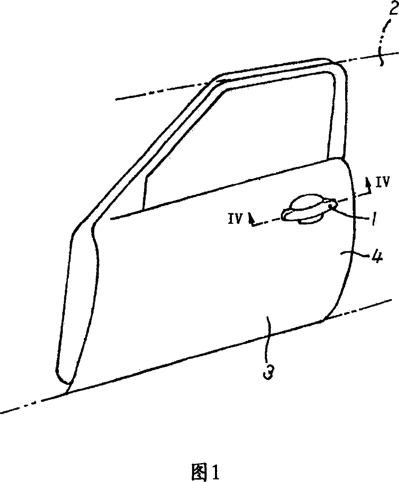
[0027] Fig. 1 shows a perspective view of a door 3 of a vehicle 2 to which a door handle according to a first embodiment of the invention is attached. In the drawing, a grip type door handle 1 is attached to a metal outer panel 4 and protrudes outward from the outer panel 4 in the vehicle width direction. The door handle 1 is operated to open and close the door 3 and is a substantially curved hollow structure. One end of the door handle 1 is rotatably supported by an outer panel 4 . An operating portion that operates a door opening and closing mechanism (not shown) is inserted into the interior of the door 3 through the outer panel 4 . The door 3 shown in Fig. 1 is a side door of the vehicle 2, however, the door handle 1 can be attached to the rear door.

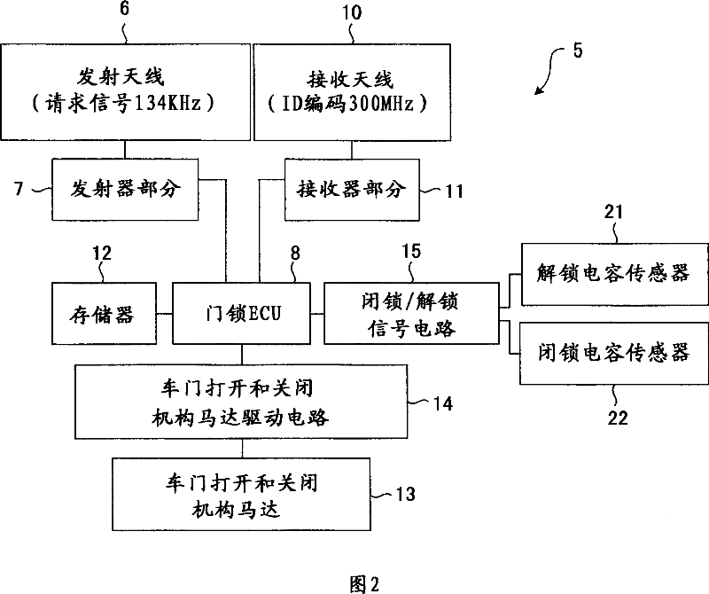
[0028] FIG. 2 shows a block diagram of an example of an in-vehicle device 5 of a smart door lock system serving as a door...


PUM


Abstract

A door handle apparatus for a vehicle includes a door handle including an outer side handle portion formed with a grip portion, a rotating portion rotatably supported by a supporting member, an operating portion operating a door opening and closing mechanism, and an encasement accommodating electronic components, an unlock electrode accommodated in the encasement and configuring an unlock capacitive sensor detecting changes of an electric capacity between the unlock electrode and the outer panel, an unlock signal circuit transmitting an unlock signal based on the changes of the electric capacity between the unlock electrode and the outer panel, and a lock electrode provided between an end of the grip portion at the side of the rotating portion and the rotating portion and configuring a lock capacitive sensor detecting the changes of the electric capacity.

Description

technical field [0001] The present invention relates to a door handle device for performing opening and closing operations. Background technique [0002] Traditionally, the vehicle user has a wireless transmitting portable unit and moves close to or away from the vehicle, using a so-called smart lock system to transmit a signal to lock or unlock the vehicle doors. The system has an on-board device attached to the vehicle. The in-vehicle device transmits electromagnetic waves (request signals) for transmitting requests to the outside of the vehicle, and receives electromagnetic waves transmitted back from the portable unit. The portable unit serves to transmit electromagnetic waves having a predetermined code back to the on-vehicle device in response to the received electromagnetic waves of the transmission request from the on-vehicle device. Then, the on-board device determines whether the returned electromagnetic code is the same as the specified code, and if the code is ...

Claims


Application Information

Patent Timeline
Patent Type & Authority Applications(China)
IPC IPC(8): E05B65/12E05B1/00E05B49/00E05B81/78E05B85/16
CPCG07C9/00309E05B81/77G07C2209/65Y10T292/57E05B81/78
Inventor 谷本哲朗永田浩一虫明荣司
Owner AISIN SEIKI KK
Why Eureka
Try Eureka