Laminated glass for vehicle
A technology for laminated glass and vehicles, applied in vehicle parts, glass/slag layered products, layered products, etc., can solve problems such as optical deformation of the intermediate layer, and achieve the effect of effective production, efficient manufacturing steps, and improved integrity
- Summary
- Abstract
- Description
- Claims
- Application Information
AI Technical Summary
Benefits of technology
Problems solved by technology
Method used
Image
Examples
no. 1 approach
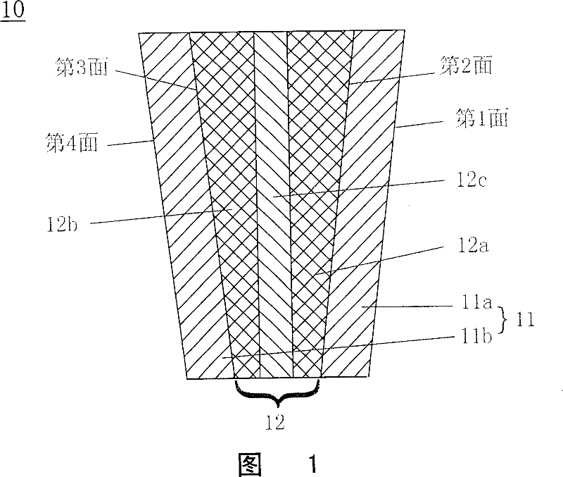
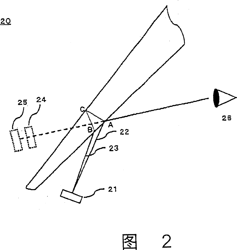
[0062] 1 and 2 are respectively an example of the structure of the laminated glass of the present invention and a cross-sectional view of a head-up display using the laminated glass.
[0063] As shown in FIG. 1, in a laminated glass 10, a multilayer interlayer 12 made of resin is sandwiched between curved laminated glass plates 11a and 11b. Each glass sheet 11 has a uniform thickness, and the thickness of the interlayer 12 has a wedge-shaped configuration in which the upper side is thicker and the lower side is thinner. Since the glass plates 11 are combined so as to sandwich the wedge-shaped interlayer sandwich 12, the positions of the first face and the second face which are the surfaces of the glass plate 11a are different from the positions of the third face and the fourth face which are the surfaces of the glass plate 11b. parallel. As a result, the laminated glass 10 has a wedge-shaped configuration in thickness.
[0064] The interlayer 12 is a multilayer film comprisi...
no. 2 approach
[0107] Fig. 4 is a cross-sectional view showing an example of the structure of the laminated glass of the present invention. In the same way as in the first embodiment, the thickness of the interlayer 12 is a wedge-shaped configuration, the upper side being thicker and the lower side being thinner, and the glass plate 11 is bonded to the wedge-shaped interlayer. As a result, the thickness of the laminated glass has a wedge-shaped configuration.
[0108] The interlayer 12 is a multilayer film comprising skin layers 12a and 12b and a sound-insulating layer 12c sandwiched between the skin layers. The interlayer 12 is bonded to the second face of the glass plate 11a and the third face of the glass plate 11b to form a layer Pressed glass 10. The surface layers 12a and 12b are each a resin layer of uniform thickness, and the sound-insulating layer 12c is sandwiched between them, having a wedge-shaped thickness configuration with a thicker upper side and a thinner lower side.
[01...
no. 3 approach
[0113] Fig. 5 is a cross-sectional view showing an example of the structure of the laminated glass of the present invention. In the same manner as in the first embodiment, the thickness of the interlayer 12 is in a wedge-shaped configuration with a thicker upper side and a thinner lower side, and the glass plate 11 is bonded to the wedge-shaped interlayer so as to sandwich the interlayer. As a result, the thickness of laminated glass 10 has a wedge-shaped configuration.
[0114] The interlayer is a multilayer film comprising skin layers 12a and 12b and a sound-insulating layer 12c sandwiched between the skin layers. The interlayer 12 is bonded to the second side of the glass sheet 11a and the third side of the glass sheet 11b to form a laminate. glass10. The surface layers 12a and 12b and the sound-insulating layer 12c each have a wedge-shaped configuration with a thicker upper side and a thinner lower side, and the sound-insulating layer 12c is composed of a resin having a h...
PUM
| Property | Measurement | Unit |
|---|---|---|
| Thickness | aaaaa | aaaaa |
| Thickness | aaaaa | aaaaa |
| Thickness | aaaaa | aaaaa |
Abstract
Description
Claims
Application Information
 - R&D
- Intellectual Property
- Life Sciences
- Materials
- Tech Scout
- Unparalleled Data Quality
- Higher Quality Content
- 60% Fewer Hallucinations
Browse by: Latest US Patents, China's latest patents, Technical Efficacy Thesaurus, Application Domain, Technology Topic, Popular Technical Reports.
© 2025 PatSnap. All rights reserved.Legal|Privacy policy|Modern Slavery Act Transparency Statement|Sitemap|About US| Contact US: help@patsnap.com


