Radial insulation laminated conductive retractor collar

A conductive slip ring, laminated technology, applied in the field of electromechanical devices, can solve the problems of increasing the radial size of the slip ring, reducing the rigidity of the insulating sleeve, and difficult to process thin-walled insulating sleeves, avoiding precision machining, increasing the Stiffness, the effect of simplifying the process

Active Publication Date: 2007-09-19
BEIJING INST OF AEROSPACE CONTROL DEVICES
View PDF0 Cites 30 Cited by
  • Summary
  • Abstract
  • Description
  • Claims
  • Application Information

AI Technical Summary

Problems solved by technology

The disadvantage is that the thin-walled insulating sleeve is difficult to process, and the insulating sleeve increases the radial dimension of the sli

Method used


Image

  • Radial insulation laminated conductive retractor collar
  • Radial insulation laminated conductive retractor collar
  • Radial insulation laminated conductive retractor collar

Examples


Embodiment 1

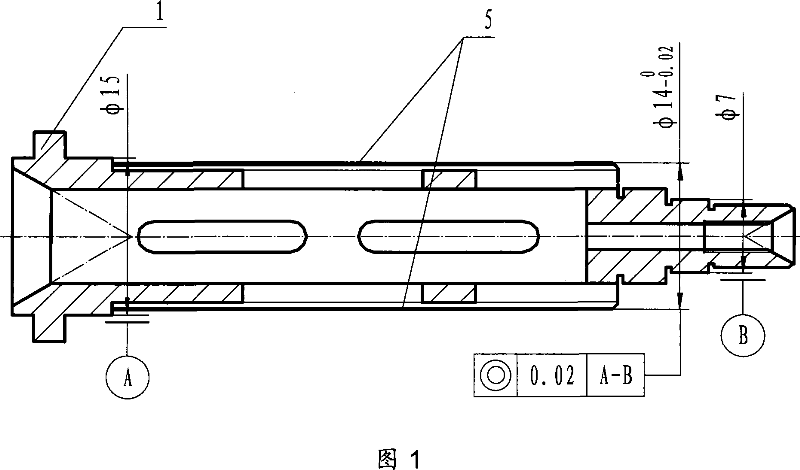
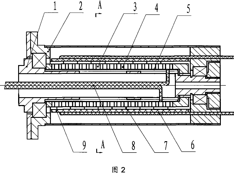
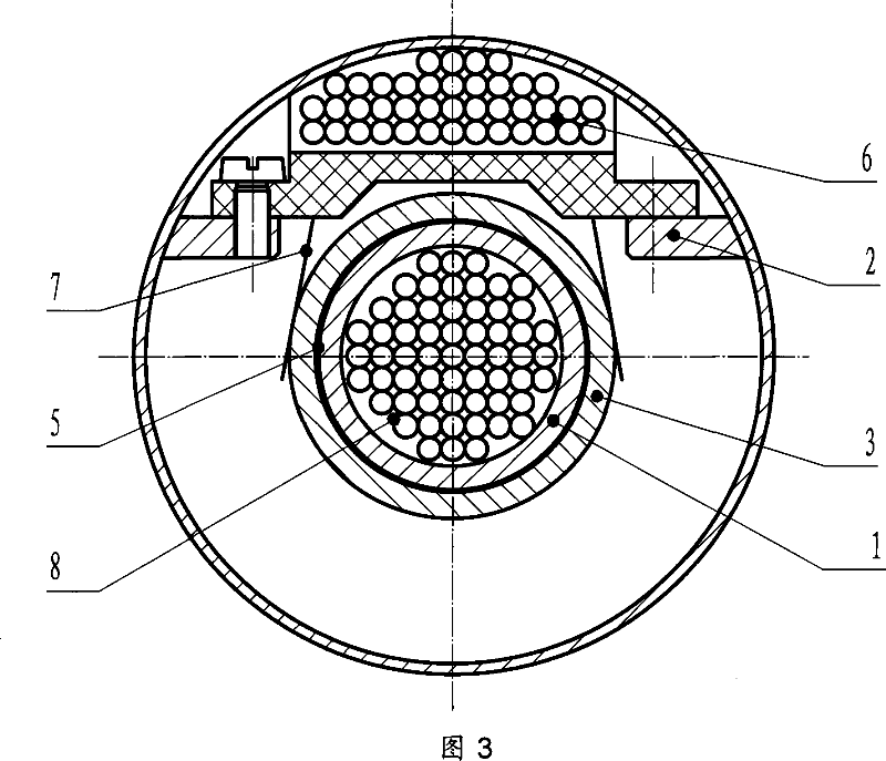
[0013] Now to process a conductive slip ring shaft with a diameter of φ14mm, first divide the slip ring shaft 1 into two sections, and set the wiring grooves for the lead wires 8 of the conductive ring pieces at a radial difference of 90°. The hollow inside of the shaft communicates, and the shaft of the slip ring is φ14 -0.02 0 If the outer circle is semi-finishing to φ13.7mm, then the reserve for coating thickness is 0.15mm;

[0014] Spray liquid Teflon polymer insulating material on the outer circle of the slip ring shaft, and cure it at a high temperature of 350°C. The two processes of spraying and curing are carried out alternately 5 times, and the temperature of high temperature curing is controlled at 350±10°C to prevent The shaft is deformed, and the thickness of the coating is left with a finishing allowance of 0.05mm;

[0015] Then, the φ15 and φ7 outer circles on the slip ring shaft are ground and finished, and the φ14 -0.02 0 The outer circle is ground and fini...

Embodiment 2

[0019] Now to process a conductive slip ring shaft with a diameter of φ14mm, first divide the slip ring shaft 1 into 10 sections, and set the wiring groove for the lead wire 8 of the conductive ring piece on the same straight line, the hollow of the wire groove and the slip ring shaft Internal communication, slip ring shaft φ14 -0.02 0 If the outer circle is semi-finishing to φ13.4mm, then the reserve for coating thickness is 0.3mm;

[0020] Secondly, spray liquid machinable glass-ceramic polymer insulating material on the outer circle of the slip ring shaft, and cure it at a high temperature at 200°C. The two processes of spraying and curing are carried out twice respectively, and the coating thickness is left with a finishing allowance of 0.08mm;

[0021] Then, the φ15 and φ7 outer circles on the slip ring shaft are ground and finished, and the φ14 -0.02 0 The outer circle is turned and finished, reaching φ14 -0.02 0 The dimensional tolerance requirements and the 0.02mm...


PUM

PropertyMeasurementUnit
Thicknessaaaaaaaaaa

Abstract

The invention provides a radial insulation laminated conductive slip ring which belongs to electrical rotary adapter. Conductive ring sheets 3 and insulation sheets 4 are interval arranged on a slip ring shaft 1, and a section of the slip ring shaft 1 surface for mounting the conductive ring sheet is coated with polymer insulation material to guarantee the insulation between the slip ring shaft 1 and the conductive ring sheet 3. A brush 7 mounted on a brush bracket 9, which is mounted on a shaft sleeve 2, tightly contacts with the conductive ring sheet 3, rolling bearings are disposed between the slip ring 1 and the shaft sleeve 2 for supporting, when the slip ring 1 rotates relative to the shaft sleeve 2, the transmission for multi-channel electrical signals between the relative rotating parts can be realized via conductive ring sheet lead-out wires 8 and brush lead-out wires 6. The invention effectively simplifies the production procedure, and reduces the radial size of the slip ring, and increases the stiffness of the shaft.

Description

technical field [0001] The present invention relates to an electromechanical device for transmitting electrical signals and electrical energy through a relative rotating sliding contact between a conductive ring and a brush. Background technique [0002] A conductive slip ring is an electromechanical device that transmits electrical signals and electrical energy through the relative rotating sliding contact between the conductive ring and the brush, also known as an electrical rotary connector. Conductive slip rings are mainly composed of conductive rods, brushes and other components. The conductive rod is composed of a slip ring shaft, a conductive ring piece and an insulating layer between the conductive ring pieces. According to the forming method of the conductive rod, the slip ring can be divided into three structural forms: the laminated slip ring, the integral glue-filled slip ring and the electrochemical deposition slip ring. The axial insulation between the conduc...

Claims


Application Information

Patent Timeline
IPC IPC(8): H01R39/64H01R39/08H01R43/10H01R39/18H01R39/24
Inventor 刘洪丰席少明
Owner BEIJING INST OF AEROSPACE CONTROL DEVICES
Why Eureka
Try Eureka