Colour switching temperature indicator

A technology of temperature indicator and predetermined temperature, applied in thermometers, thermometers with physical/chemical changes, instruments, etc., can solve the problem that the temperature indicator is not given, and achieve the effect of low processing cost and compact design

Inactive Publication Date: 2007-09-19
KONINK PHILIPS ELECTRONICS NV
View PDF2 Cites 6 Cited by
  • Summary
  • Abstract
  • Description
  • Claims
  • Application Information

AI Technical Summary

Problems solved by technology

Furthermore, this type of temperature indicator gives no information as to which part of the surface is hot if the whole surface or only a part of it is hot

Method used


Image

  • Colour switching temperature indicator
  • Colour switching temperature indicator
  • Colour switching temperature indicator

Examples


Embodiment Construction

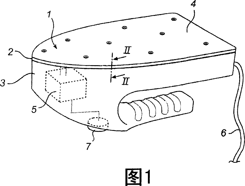
[0039] Fig. 1 schematically shows a temperature indicator 1 according to a first embodiment of the invention. The temperature indicator 1 covers the entire bottom 2 of the iron 3. As described below, the temperature indicator 1 includes a light-emitting diode and a light-emitting electrochemical cell, which together form a light-emitting laminate 4, and the AC power source 5 is suitable for driving the light-emitting laminate 4 with a low-frequency AC voltage. The AC power source 5 is connected to the main power system of the iron 3 (not shown in FIG. 1) and always provides AC voltage to the light-emitting laminate 4 when the cable 6 of the iron 3 is connected to the power source. As described below, the AC voltage frequency regulator 7 can be optionally included in the temperature indicator 1 so that the temperature at the time of changing the light emission can be finely adjusted.

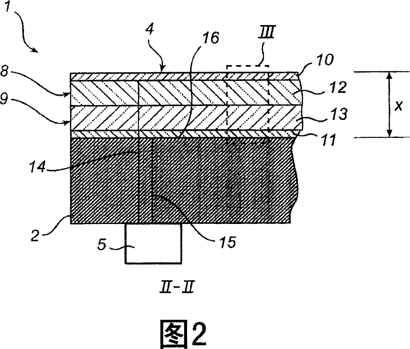
[0040]FIG. 2 is a cross-section showing the light-emitting laminate 4, which has the shape of a t...


PUM


Abstract

A temperature indicator (101) is adapted to be provided on a surface (116) for providing a first type of light emission and a second type of light emission (L2). The temperature indicator (101) comprises a light-emitting diode (108) for providing said first type of light emission and a light-emitting electrochemical cell (109) for providing said second type of light emission (L2). The light-emitting electrochemical cell (109) has a first electrode (120), a second electrode (121) and a second light-emitting layer (113) being sandwiched between them and comprising a matrix and ions being movable in the matrix, the mobility of said ions in said matrix being temperature dependent. A power source (105) is adapted for driving the cell (109) with an AC voltage, the frequency of which is tuned in such a way that the cell (109) provides said second type of light emission (L2) when the surface temperature exceeds a certain level.

Description

Technical field [0001] The present invention relates to a temperature indicator adapted to be placed on a surface for providing a first type of light emission and a second type of light emission, the latter being emitted when the surface temperature is higher than a predetermined temperature. Background technique [0002] In many appliances, high temperatures are involved during use. Such appliances are, for example, irons, electric kettles, hot plates, oven windows, frying pans, ovens, and split cores. In order to avoid injury to the person using the appliance, such as burns, the person using the appliance needs to have an indicator to indicate that the appliance is hot and must be careful. This high temperature indication is generally given by having a temperature sensor, a control unit coupled to the sensor, and one or more lamps, and when the sensor reaches a predetermined temperature, the control unit lights these lamps. An example of such a system can be found in US 6,396,0...

Claims


Application Information

Patent Timeline
Patent Type & Authority Applications(China)
IPC IPC(8): G01K11/12
CPCG01K11/12
Inventor 爱德华·J.·迈耶勒内·T.·韦拉尔夫·库尔特
Owner KONINK PHILIPS ELECTRONICS NV
Why Eureka
Try Eureka