
High-voltage capacitor

A technology of high-voltage capacitors and capacitors, applied in the direction of capacitors, fixed capacitors, multiple fixed capacitors, etc., can solve problems such as restrictions, and achieve the effects of avoiding voltage differences, compact placement, and compact structure

Inactive Publication Date: 2007-09-19
SIEMENS AG
View PDF2 Cites 3 Cited by
  • Summary
  • Abstract
  • Description
  • Claims
  • Application Information

AI Technical Summary

Problems solved by technology

Such voltage differences are undesirable, and they result in restrictions on the maximum voltage permitted to be released across the high voltage capacitor terminals

Method used


Image

  • High-voltage capacitor
  • High-voltage capacitor
  • High-voltage capacitor

Examples


Embodiment Construction

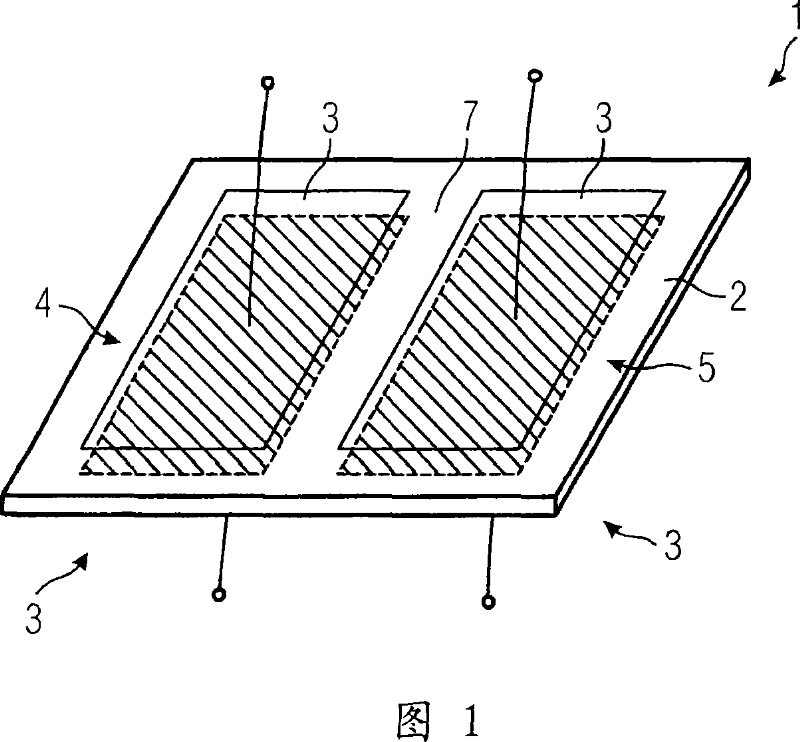
[0019] Fig. 1 shows an embodiment of a capacitor element 1 according to the invention before it is wound. The illustrated capacitor element 1 consists of an insulating or dielectric film 2, on both sides of which a thin metal foil 3 is applied as an electrically conductive coating. A total of four metal foils 3 can be seen here, two of which are located opposite each other in pairs on different sides of the insulating film 2 and thus form a first individual capacitor 4 and a second individual capacitor 5 . The individual capacitors 4 and 5 are insulated from each other by an insulating spacer 7 extending between the individual capacitors 4 and 5 . By mounting the two individual capacitors on the insulating or dielectric film 2, the individual capacitors 4 and 5 can be designed substantially symmetrically to each other.

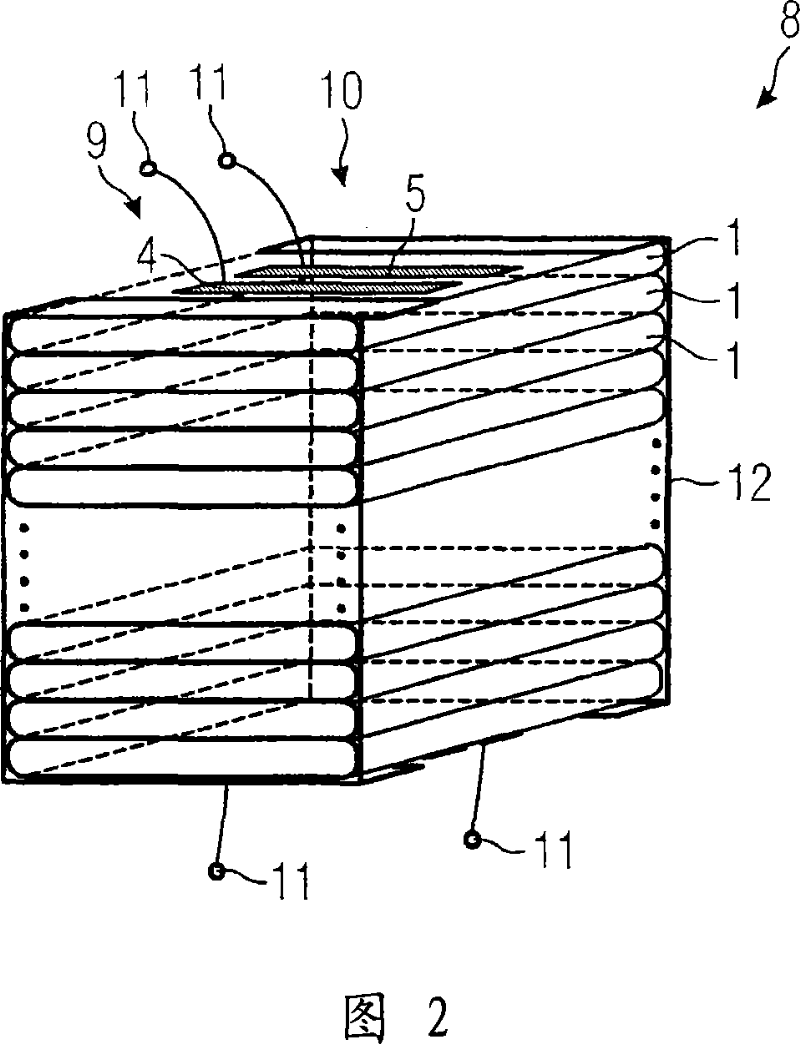
[0020] FIG. 2 shows an exemplary embodiment of an active component 8 consisting of capacitor elements 1 arranged one above the other. The capacitor elements...


PUM


Abstract

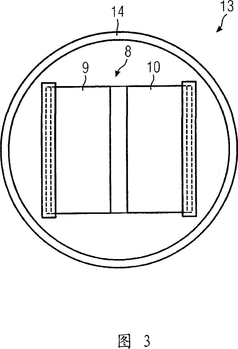
The invention relates to a high-voltage capacitor (13) which is used to transmit energy and which comprises an insulator housing (14), wherein at least two serially connected capacitors (9, 10), which are mounted in parallel, are arranged. Said capacitors are made of, respectively, a serial connection of individual capacitors (4,5) which are embodied as stackable capacitor elements (1). The aim of the invention is to provide a high-voltage capacitor which is compact and economical. Each capacitor element (1) comprises several individual capacitors (4, 5) which are maintained in an isolated manner, whereby the number corresponds to the number of serially connected capacitors (9,10), such that said serially connected capacitors (9,10) are formed by one stack of capacitor elements (1).

Description

technical field [0001] The invention relates to a high voltage capacitor for power distribution. [0002] High-voltage capacitors for power distribution are known, for example, from DE 2847775 A1. The high-voltage capacitors disclosed there have a cylindrical or prismatic insulating housing in which a capacitor series circuit is arranged. A capacitor series circuit consists of capacitor elements whose individual capacitors are connected in series with each other via connectors. Here, the capacitor elements have flat rolls of metal strips, which serve as the electrode faces of the individual capacitors. These metal strips are separated from each other by a dielectric or insulating layer, where the insulating layer consists of a plurality of dielectric films. The capacitor series circuit is arranged in a support, and the support ensures the mechanical fixation of the capacitor series circuit. Background technique [0003] DE19510624C1 describes a wound capacitor in which a...

Claims


Application Information

Patent Timeline
IPC IPC(8): H01G4/38
CPCH01G4/385H01G4/38
Inventor 西格弗里德·伯克尔斯蒂芬·海恩诺伯特·科克冈特·特罗詹
Owner SIEMENS AG
Learn More