
A Conjugate Iron Core for 24-pulse Rectifier Transformer

A technology of pulse wave rectification and transformers, which is applied in the field of transformers, can solve the problems of high manufacturing cost of rectifier transformers, high transformer losses, and large unit footprint, and achieve low manufacturing costs, low transformer losses, and small footprints.

Active Publication Date: 2018-12-18
HENAN BULL TRANSFORMER CO LTD
View PDF7 Cites 0 Cited by
  • Summary
  • Abstract
  • Description
  • Claims
  • Application Information

AI Technical Summary

Problems solved by technology

[0005] The above two cases are equivalent to two or more transformers. The biggest disadvantages are the high manufacturing cost of the rectifier transformer, the large area of ​​the unit, and the high loss of the transformer. For a single machine to achieve 24-pulse rectification, it must A special wiring method is adopted to make the minimum phase difference between the corresponding phases of the primary side and the secondary side be 15°. The best way to achieve this goal is to shift the phases by +7.5 degrees and -7.5 degrees respectively through the grid-side input winding and using the extension triangle connection.

Method used


Image

  • A Conjugate Iron Core for 24-pulse Rectifier Transformer
  • A Conjugate Iron Core for 24-pulse Rectifier Transformer
  • A Conjugate Iron Core for 24-pulse Rectifier Transformer

Examples


Embodiment Construction

[0022] The present invention is described in conjunction with accompanying drawing and specific embodiment:

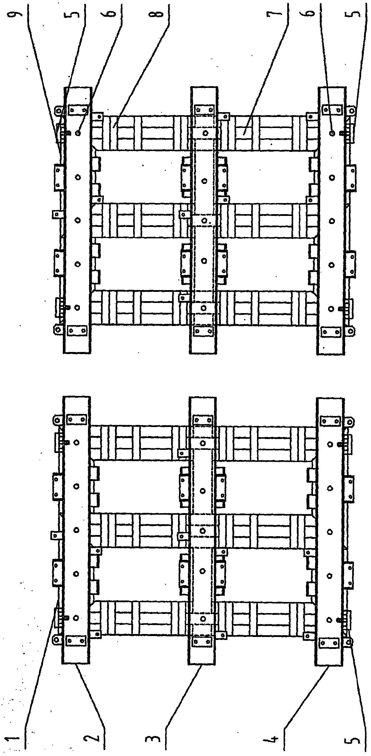
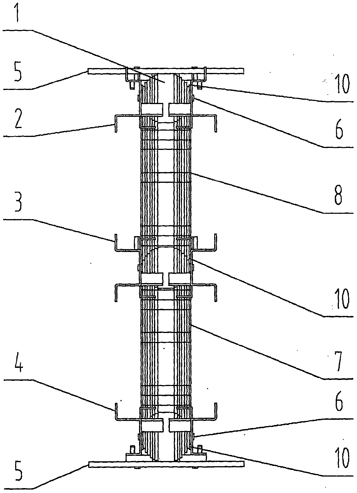
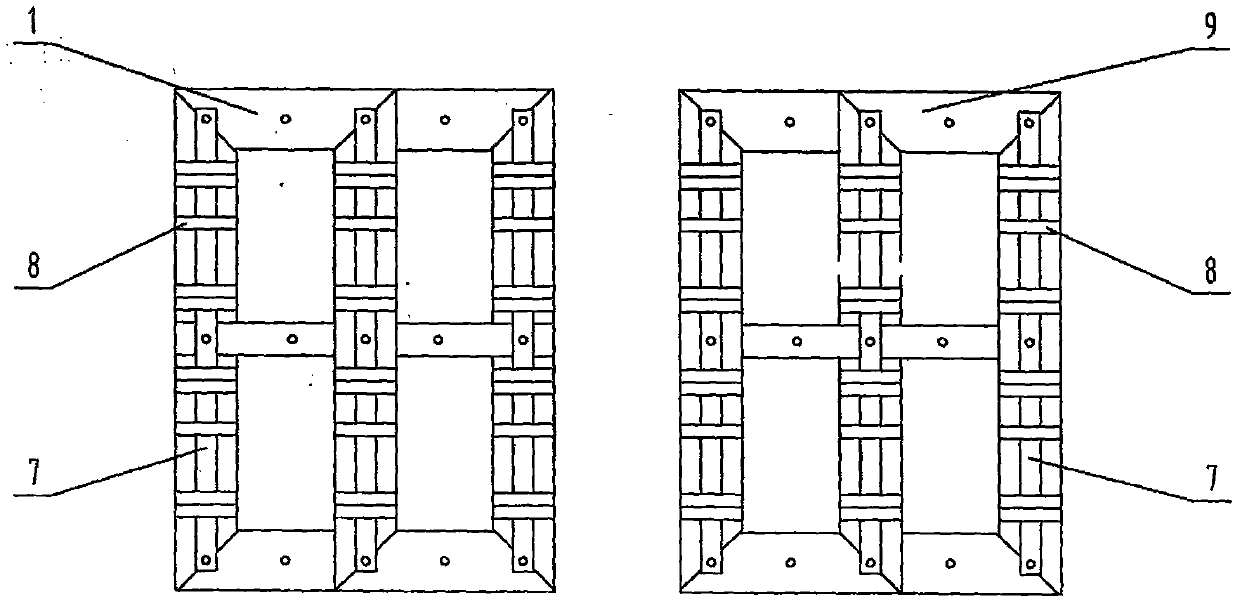
[0023] Such as figure 1 and figure 2 As shown, the 24-pulse rectifier transformer of the present invention uses a conjugate core, which includes a first core assembly 1 and a second core assembly 9 vertically arranged in a left-right symmetrical manner, and the first core assembly and the second core assembly The components all include a square-shaped iron core, and the upper clamping parts 2 and middle clamping parts 3 are respectively arranged on the front and rear sides of the iron core at equal intervals from top to bottom, and are used to clamp the upper, middle and lower horizontal core parts of the iron core. And the lower clip 4, and the anchors 5 arranged at the upper and lower ends of the iron core; stainless steel pull plates 7 are arranged on the front and rear sides of the vertical iron core column of the iron core, and the upper, middle and lower clips ...


PUM


Abstract

The invention provides a conjugate iron core for a 24-pulse-wave rectifier transformer. The conjugate iron core comprises a first iron core assembly and a second iron core assembly which are vertically arranged in a bilateral symmetry mode. The first iron core assembly and the second iron core assembly each comprise an iron core shaped like the Chinese character 'tian', an upper clamp, a middle clamp, a lower clamp and foot margins, the upper clamps, the lower clamps and the lower clamps are arranged on the front faces and the rear faces of the iron cores respectively at equal intervals from top to bottom and used for clamping the upper transverse iron core portions, the middle transverse iron core portions and the lower transverse iron core portions of the iron cores, and the foot margins are arranged at the upper ends and the lower ends of the iron cores. Stainless steel pull plates are arranged on the front face and the rear face of a vertical iron core column of each iron core, insulation clamps are arranged at the joint parts of the upper clamps and the stainless steel pull plates, between the middle clamps and the combination portion of the stainless steel pull plates and between the lower clamps and the combination portion of the stainless steel pull plates, the stainless steel pull plates, the insulation clamps, the upper clamps, the lower clamps and the lower clamps are tightened and fixed together through a plurality of pull plates shaft heads arranged in the horizontal direction of the clamps, and the stainless steel pull plates and the iron core columns are wound together through binding belts wound in the vertical direction of the iron core columns.

Description

technical field [0001] The invention belongs to the technical field of transformers, and in particular relates to a conjugate core for a single-machine 24-pulse rectifier transformer. Background technique [0002] As is known, a rectifier transformer is a power transformer of a rectifier device. The characteristic of the rectifier is that the primary side inputs AC, and the secondary side outputs DC after passing through the rectifier element. Since the rectifier winding current is non-sinusoidal and contains many high-order harmonics, in order to reduce the harmonic pollution to the grid and improve the power factor, the pulse number of the rectifier must be increased, which can be solved by phase shifting. The purpose of phase shifting is to make a phase shift between the voltages of the same-named terminal lines of the secondary winding of the rectifier transformer. For a three-phase power system, the power supply is distributed 360° in space, and the phases of A, B, an...

Claims


Application Information

Patent Timeline
Patent Type & Authority Patents(China)
IPC IPC(8): H01F27/26H01F27/245
Inventor 刘志敏吕继兵曾理森席光明
Owner HENAN BULL TRANSFORMER CO LTD
Learn More