Vapor deposition source and vapor deposition apparatus

A vapor deposition and steam technology, applied in lighting devices, light sources, electric light sources, etc., can solve the problems of difficult flow through the flow path, unable to quickly reach the opening, etc., and achieve the effect of high-speed vapor deposition.

Active Publication Date: 2007-09-26
CANON KK
View PDF3 Cites 5 Cited by
  • Summary
  • Abstract
  • Description
  • Claims
  • Application Information

AI Technical Summary

Problems solved by technology

And, when the gas evaporated from the raw material placed on the protrusion collects on the flow path at the center of the container and it is difficult for the gas to flow through the flow path compared with the gap above and below the protrusion, the gas evaporated from the raw material placed on the protrusion Gas cannot reach the opening quickly

Method used


Image

  • Vapor deposition source and vapor deposition apparatus
  • Vapor deposition source and vapor deposition apparatus
  • Vapor deposition source and vapor deposition apparatus

Examples


no. 1 example

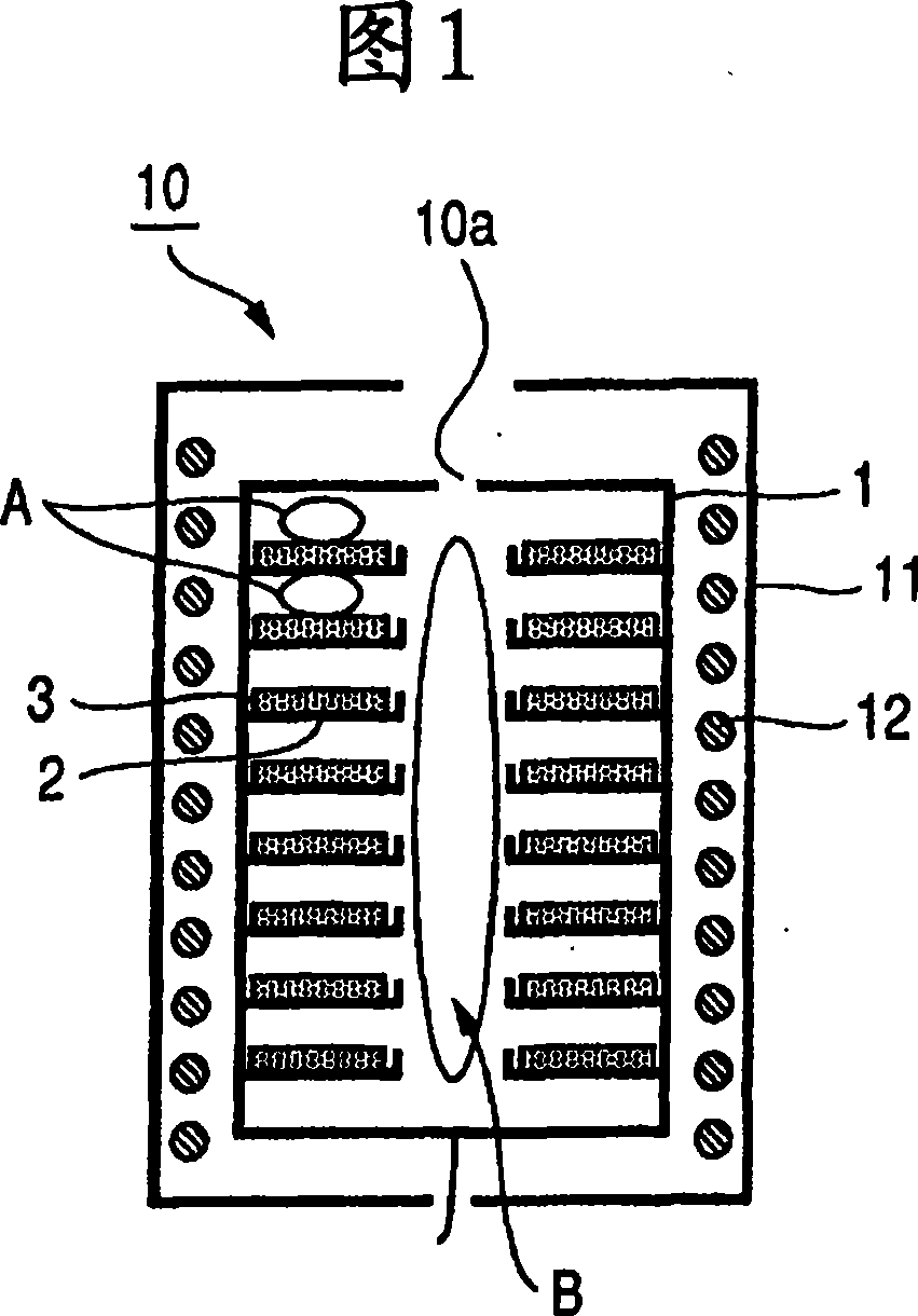
[0043] Fig. 1 shows a first embodiment, and a crucible 1 is supported by a structure (not shown) and heated by a heater 12 by radiation. The thermostat and power supply control the power of the heater 12 by using a thermocouple to measure the temperature of the bottom of the crucible 1 . The reflector 11 outside the heater 12 is used to concentrate the radiant heat from the heater 12 onto the crucible 1 . A thin vapor deposition material 3 is mounted on a donut-shaped plate 2 protruding inwardly from the inner wall of the crucible 1 . Each of the donut-shaped plates 2 is separated by a fixed distance from the adjacent upper and lower donut-shaped plates 2 .

[0044] In this embodiment, a 1 mm thick vapor deposition material 3 is mounted on each of the donut-shaped flat plates 2 . Each donut plate 2 has a diameter of 40 mm and a central circular hole with a diameter of 10 mm. Eight donut-shaped flat plates 2 are stacked coaxially with a distance of 5 mm. The flow space A be...

no. 2 example

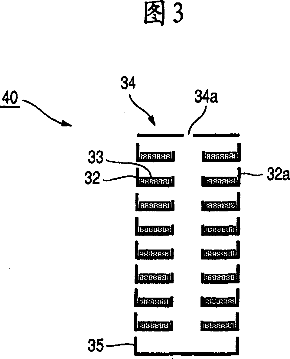
[0053]3 and 4 show a vapor deposition source 40 according to a second embodiment. As shown in the enlarged view of FIG. 3, each donut-shaped flat plate 32 of the vapor deposition source 40 has a side wall 32a, and the donut-shaped flat plate 32 integrated with the side wall 32a is individually provided on each layer. . Alq3 was mounted as a vapor deposition material 33 on a donut-shaped flat plate 32 coaxially stacked as shown in FIG. 4 . Then, a top cover 34 having a central hole 34a is provided on top, and a bottom plate 35 is provided on the bottom. The side wall 32a, the top cover 34 and the bottom plate 35 of the stacked donut-shaped flat plate 32 are adjusted so that they have the same function as the crucible 1 in the first embodiment, and then, the heater 42 is arranged outside the side wall 32a . That is, the vapor deposition source shown in FIG. 4 is adjusted so that a plurality of structures are stacked vertically in which the frame body is integrated with the do...


PUM

PropertyMeasurementUnit
thicknessaaaaaaaaaa

Abstract

An object of the present invention is to reduce splash generated in a vapor deposition source and carry out vapor deposition at a stable, high vapor deposition speed. The vapor deposition according to the present invention is carried out by vertically stacking a plurality of doughnut-shaped flat plates in a crucible, mounting thin vapor deposition material on the doughnut-shaped flat plates, using heaters that surround the crucible to heat the vapor deposition material on the doughnut-shaped flat plates, allowing the vapor generated from the vapor deposition material to flow through a flow space A at each layer into a vertical flow path B, and discharging the vapor from an opening at the top of the flow path B toward a substrate to be deposited. The conductance of the flow space A is smaller than the conductance of the flow path B.

Description

technical field [0001] The present invention relates to a vapor deposition source and a vapor deposition apparatus for use in a vapor deposition apparatus for forming a film of an organic EL pattern such as an organic element mounted in an organic EL display. Background technique [0002] Since the future trend of display devices is characterized by a thin profile, quick response, and wide viewing angle, organic EL displays are attracting attention as display devices that provide high luminance and low power consumption and replace liquid crystal displays. Methods for manufacturing organic EL displays are roughly classified into two methods. One method involves vapor deposition using a mask to form a film made of a low-molecular-weight organic EL material, while the other method involves forming ribs on a substrate in advance and then using inkjet printing or the like to deposit a high-molecular-weight organic EL material. The EL material is fed into the recess surrounded b...

Claims


Application Information

Patent Timeline
Patent Type & Authority Applications(China)
IPC IPC(8): C23C14/24C23C14/50
CPCC23C14/243C23C14/12H05B33/10
Inventor 吉川俊明真下精二福田直人
Owner CANON KK
Why Eureka
Try Eureka