Electroplating tank

A technology of electroplating tank and electroplating solution, which is applied in the direction of plating tanks, circuits, electrical components, etc., can solve the problems of difficult control of uniformity, and achieve the effects of consistent surface loss, extended length, and reduced quantity

Active Publication Date: 2016-08-17
SOLTRIUM TECH LTD SHENZHEN
View PDF6 Cites 0 Cited by
  • Summary
  • Abstract
  • Description
  • Claims
  • Application Information

AI Technical Summary

Problems solved by technology

[0011] The purpose of the present invention is to provide an electroplating tank, aiming to solve the difficult problem in the prior art that the uniformity of copper or gallium or indium or selenium is difficult to control when depositing copper or gallium or indium or selenium on the substrate by non-vacuum electroplating deposition method

Method used


Image

  • Electroplating tank
  • Electroplating tank
  • Electroplating tank

Examples


Embodiment Construction

[0073] In order to make the object, technical solution and advantages of the present invention clearer, the present invention will be further described in detail below in conjunction with the accompanying drawings and embodiments. It should be understood that the specific embodiments described here are only used to explain the present invention, not to limit the present invention.

[0074] The implementation of the present invention will be described in detail below in conjunction with specific drawings.

[0075] Such as Figure 2-4a Shown is the preferred embodiment provided by the present invention.

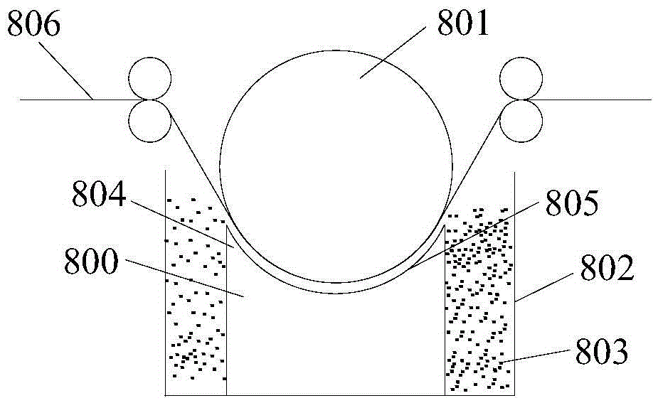
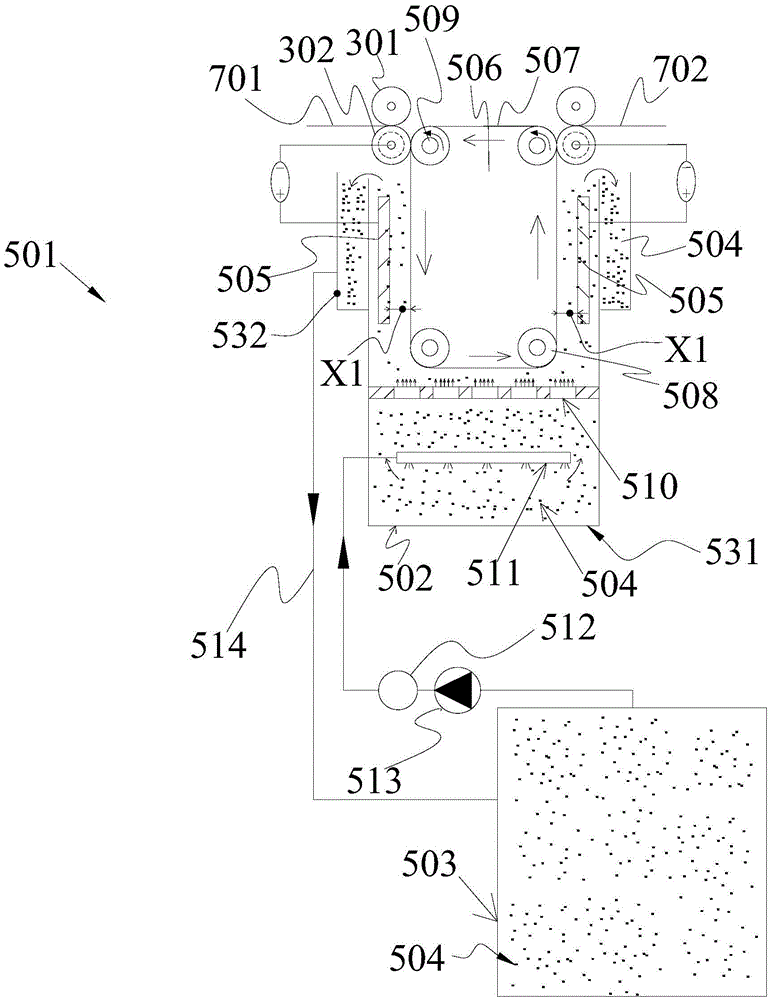
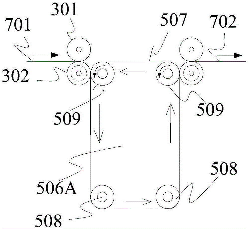
[0076] An electroplating tank provided in this embodiment is a working tank where electroplating occurs, and is used to deposit copper or gallium or indium or selenium on a surface of a substrate. It can be understood that the substrate is conducive to depositing copper or gallium or The indium or selenium element absorbing layer is made of conductive material, such as alumin...


PUM


Abstract

The invention belongs to the technical field of preparation of solar cells, and in particular relates to an electroplating bath, which is used for depositing elemental copper, gallium, indium or selenium or a copper, gallium, indium or selenium alloy on the surface of a substrate. The electroplating bath comprises an electroplating branch bath and a master bath, wherein the electroplating branch bath is provided with an accommodation cavity for containing an electroplating solution; anodes immersed in the electroplating solution are hung on the lateral surfaces of the electroplating branch bath; a conveying device for carrying the substrate to synchronously move is arranged on the middle part of the electroplating branch bath; the anodes are arranged on the two sides of the conveying device; parts, opposite to the anodes, on the two lateral surfaces of the conveying device are immersed in the electroplating solution; the substrate is attached to the lateral surfaces of the conveying device, and is opposite to the anodes when passing through the electroplating branch bath. According to the electroplating bath, the length of an electroplating production line is reduced, and a small space is occupied; the elemental copper, gallium, indium or selenium or the copper, gallium, indium or selenium alloy is deposited on the front surface of the substrate only, so that few process steps are required; the anodes are opposite to the substrate, so that the uniformity and smooth finish of the surface of a deposited CIGS (copper, indium, gallium and selenium) absorption layer are ensured.

Description

technical field [0001] The invention belongs to the technical field of manufacturing solar cell equipment, in particular to a roll-to-roll electroplating tank. Background technique [0002] CIGS (copper indium gallium selenide) thin film solar cells have excellent light absorption constant, only need 1.5 micron ultra-thin absorption layer, stable photoelectric conversion efficiency, wide spectral response range, adjustable energy band, strong radiation resistance, no light It has the advantages of light-induced gain, low-light gain, light weight, low cost, and easy installation, which have become the focus of research in the field of solar energy. Its typical structure is: metal back electrode Mo layer, CIGS absorption layer, buffer layer CdS, window layer high resistance i:ZnO, low resistance ZnO:Al, MgF2 anti-reflection film and Ni-Al gate electrode. [0003] The CIGS absorbing layer is composed of four elements: Cu, In, Ga, and Se. The photoelectric conversion efficiency...

Claims


Application Information

Patent Timeline
Patent Type & Authority Patents(China)
IPC IPC(8): C25D7/06C25D17/02H01L31/18
CPCY02P70/50
Inventor 胡志刚李德林
Owner SOLTRIUM TECH LTD SHENZHEN
Why Eureka
Try Eureka