Balancing a nipper mechanism in a combing machine

A combing machine and nipper shaft technology, applied in the direction of combing machine, textile and paper making, fiber processing, etc., can solve the problem of additional maintenance of the device, and achieve the effect of full clamping effect

Inactive Publication Date: 2007-09-26
MASCHINENFABRIK RIETER AG
View PDF1 Cites 4 Cited by
  • Summary
  • Abstract
  • Description
  • Claims
  • Application Information

AI Technical Summary

Problems solved by technology

[0006] Although vibrations can be reduced or attenuated by the proposed means for vibration damping, this solution however requires additional means

Method used


Image

  • Balancing a nipper mechanism in a combing machine
  • Balancing a nipper mechanism in a combing machine
  • Balancing a nipper mechanism in a combing machine

Examples


Embodiment Construction

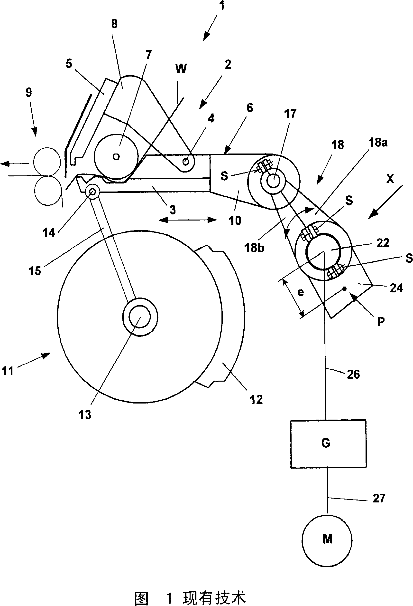
[0036] Fig. 1 schematically shows the structure of a combing head 1, which has a nipper assembly 2 provided with a lower nipper 3 and an upper nipper 5 pivotally mounted on the lower nipper around a rotation axis 4. The nipper 5 is in this case connected to two pivot arms 8 which are pivotally mounted on the swivel axis 4 . The lower nipper 3 is fixed in the nipper mount 6 . A rotatably mounted feeding cylinder 7 is arranged above the lower nipper 3, which conveys or feeds lap sheets W supplied by laps not shown in the direction of the detaching roller 9 arranged downstream at regular intervals .

[0037] In the illustrated embodiment, the nipper assembly 2 is in the front position in which it is open and performing splitting and splicing operations. On the nipper mount 6, pivoting arms 15 are mounted rotatably on both sides in the region of the lower nipper 3, in each case on the shaft 14, and at their other end at the end of the circular comb 11. on axis 13. For the comb...


PUM


Abstract

The invention relates to a combing machine comprising at least one comb head (1) with a pincers unit (2) under any circumstances, which is pivotably mounted around at least one axis (13) for the implementation of a back and forth motion and with a rotatably-mounted pincers shaft (22), which runs parallel to the axis and to which at least one swivel arm (18) is non-rotatably secured, which is drive-connected with the pincer unit (2) via corresponding device(17), and balance weights intended in the area of the swivel arms (18) and the pincers shaft (22) for the compensation of the flywheel mass of the pincer unit. In order to reduce the inertial moment of the balance weights, carding circulation of higher numbers can be realized without exceeding critical moment limit. The balance weights (20, 30) are formed or attached in such a manner that the distances (e1, e2) of the centers of gravity (P1, P2) of the respective balance weight to the rotation axis (D) of the pincer shaft (22) are 35mm-60 mm.

Description

technical field [0001] The invention relates to a combing machine having at least one combing head with in each case a nipper assembly pivotally mounted on at least one shaft for reciprocating movement and having a rotatably mounted A nipper shaft, which extends parallel to the axis and on which is fixedly mounted for rotation at least one pivot arm, which is driven by a corresponding device-connected to the nipper assembly for compensating the nipper assembly Compensation weights for the weight of the flywheel are provided in the area of ​​the pivot arm and nipper shaft. Background technique [0002] The function and schematic arrangement of the comber nipper assembly can be obtained, for example, from the document "Die Kurzstapelspinnerei; Band 3: Kammeri, Strecken, Flyer of "The Textile Institute-ISBN 3-908.059-01-1" ["Short staple spinning; , drafting, flyer of the Textile Institute-ISBN 3-908.059-01-1”] on pages 22 to 26. [0003] The nipper assembly performs a recipr...

Claims


Application Information

Patent Timeline
IPC IPC(8): D01G19/06D01G19/16
CPCD01G19/16
Inventor J·普伦T·佐林格
Owner MASCHINENFABRIK RIETER AG
Why Eureka
Try Eureka