Screen display control device and control method for screen displaying thereof

A screen display and control device technology, applied to static indicators, cathode ray tube indicators, instruments, etc., can solve problems such as user inconvenience

Inactive Publication Date: 2007-09-26
HTC CORP
View PDF0 Cites 18 Cited by
  • Summary
  • Abstract
  • Description
  • Claims
  • Application Information

AI Technical Summary

Problems solved by technology

However, this method of use must be operated with both hands at the same time, and when using it, the

Method used


Image

  • Screen display control device and control method for screen displaying thereof
  • Screen display control device and control method for screen displaying thereof
  • Screen display control device and control method for screen displaying thereof

Examples


Embodiment Construction

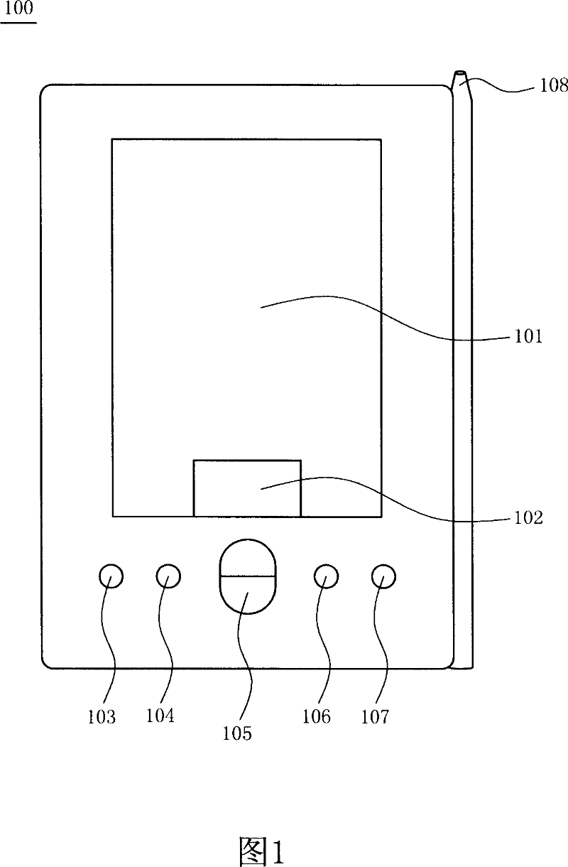
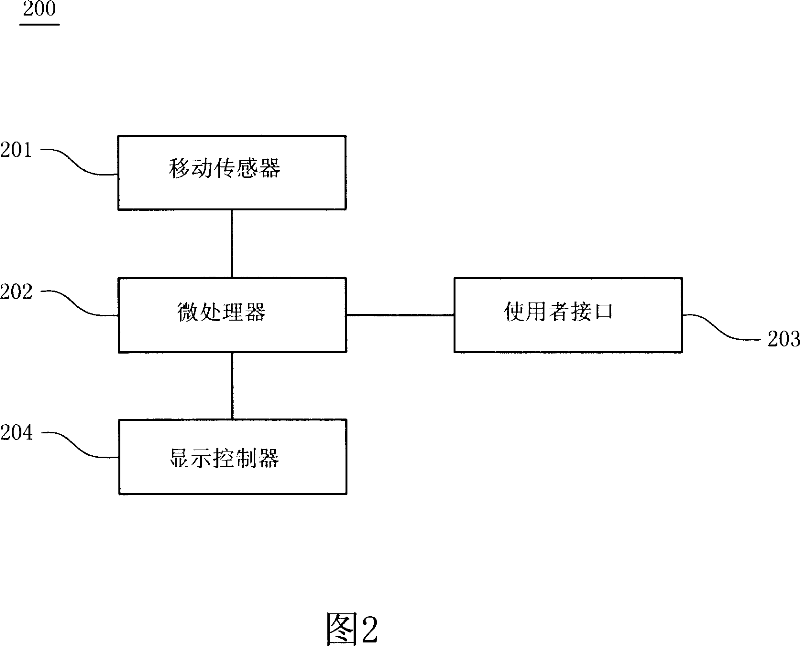
[0036] FIG. 2 is a schematic diagram of an on-screen display control device according to a preferred embodiment of the present invention. The screen display control device 200 can be applied to a portable electronic device, such as a mobile phone, a personal digital assistant (personal digital assistants, PDA), a portable computer, and the like.

[0037] The screen display control device 200 of the present invention includes a motion sensor 201 , a microprocessor 202 and a display controller 204 . Wherein the motion sensor 201 is, for example, a 2-axle accelerator, a 3-axle accelerator, an inclinometer or a compass sensor, which is mainly used to detect The movement status of the portable electronic device, and correspondingly send a movement parameter value. The microprocessor 202 is coupled to the movement sensor 201, and stores a display command inside it, wherein the relationship between the display command and the movement parameter value can be pre-programmed in the mic...


PUM


Abstract

This invention discloses one screen display control device and its method wherein, the device is in one electron device and comprises the following parts: one drive sensor to sense the portable electron device mobile parameters; one microprocessor with each mobile parameter responding to certain page position; when the micro processor receives one mobile parameters sent from sensor to trigger display order; the display order is sent to one display controller to execute one special page displacement.

Description

technical field [0001] The invention relates to a method and device for controlling screen display, in particular to a method and device for controlling screen display by rotating a fuselage. Background technique [0002] Portable electronic devices generally use buttons located around the electronic device or through a stylus and a touch screen to perform various input controls. FIG. 1 shows a schematic diagram of a traditional portable electronic device 100, including a display screen 101, a handwriting input area 102, various input buttons 103, 104, 105, 106 and 107, as well as the Stylus 108 etc. In operation, a series of control buttons are usually pressed to input information or trigger a specific function of the portable electronic device 100 for processing. [0003] When a portable electronic device has more additional functions, the number of additional control buttons is usually added to control these additional functions. However, such a design will inevitably ...

Claims


Application Information

Patent Timeline
IPC IPC(8): G09G5/00G09G5/34G09G5/36G09G5/395
CPCG06F1/1694G06F1/169G06F2200/1637G06F1/1626
Inventor 许志风高翊峰吴国祯黄明三王景弘
Owner HTC CORP
Why Eureka
Try Eureka