
Foam pump

A foam pump and pump body technology, applied in the field of foam pumps, can solve the problems of poor foaming effect and the inability to change the amount of foam sprayed according to needs, etc.

Pending Publication Date: 2021-01-05
NINGBO SHENGJIE SPRAY
View PDF1 Cites 2 Cited by
  • Summary
  • Abstract
  • Description
  • Claims
  • Application Information

AI Technical Summary

Problems solved by technology

[0005] The above technical solution discloses a pressure spring in which the elastic body is a spiral, and the pressure spring is made of rubber or plastic material at one time, and the thread body is hollow or solid; although the technical solution uses rubber or plastic springs, because it adopts a helical spring Although the spring adopts an external structure, it also has a certain inner cavity of the cylinder during use, and the gas inside the cylinder can only be mixed with the liquid when it reaches a certain pressure during the downward pressure process to achieve a certain foaming effect. The mixed foaming effect of gas and liquid is poor, and the amount of foam spray cannot be changed according to needs, etc.

Method used


Image

  • Foam pump
  • Foam pump
  • Foam pump

Examples


Embodiment 1

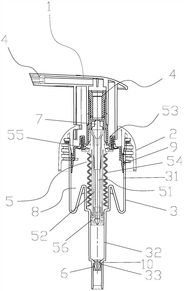
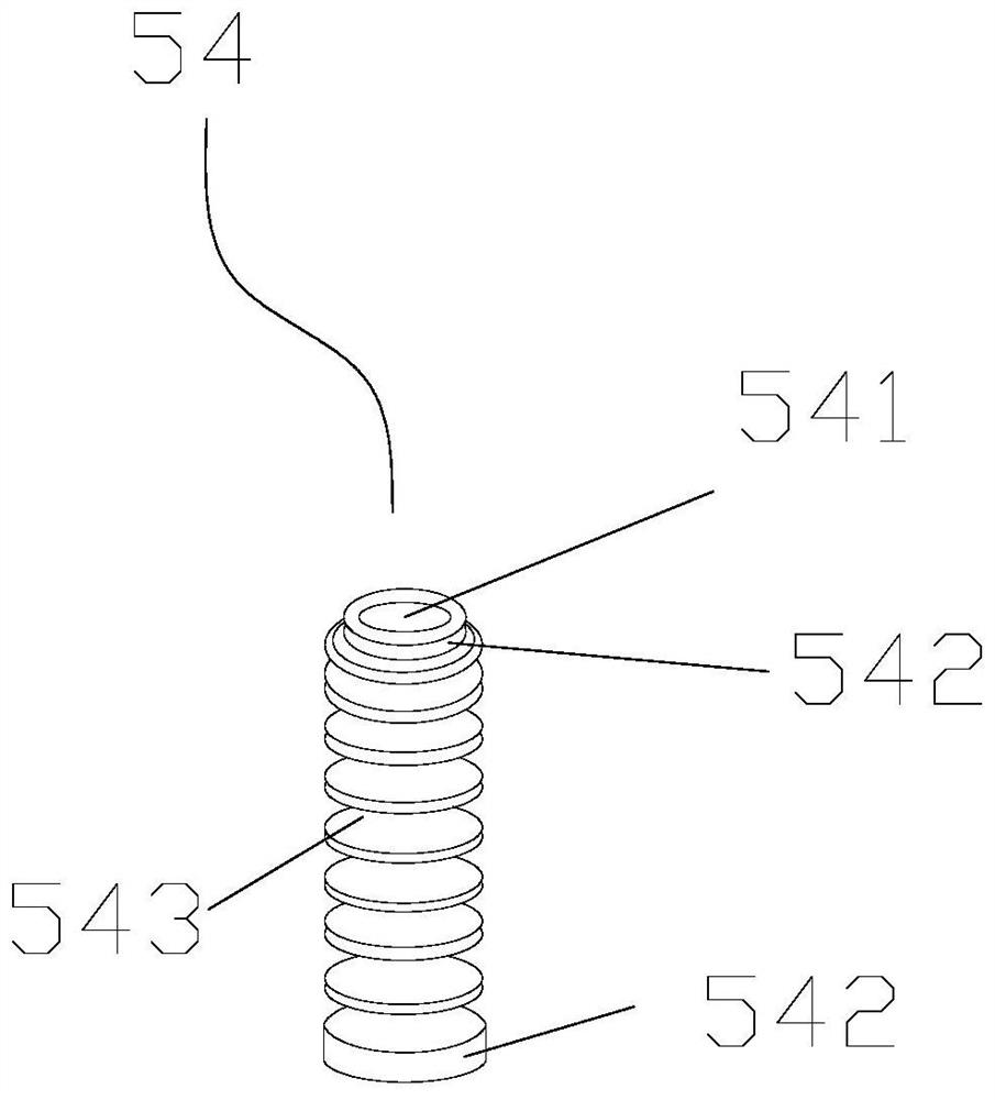
[0064] exist figure 1 , figure 2 In the shown embodiment, a kind of foam pump, all parts of this foam pump all adopt the all-plastic structure that can recover, including:

[0065] Press the pump head 1, which is used to press the operating parts for foaming and foaming;

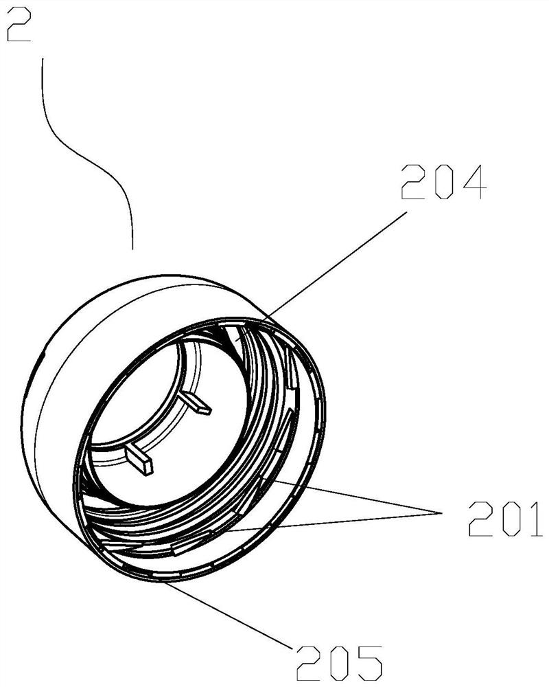
[0066] The screw cap 2 is used to connect the pump body and the liquid container 11 and the connecting parts for positioning and pressing the pump head;

[0067] The pump body 3 is the main part of the foam pump. The pump body 3 is connected with the screw cap 2 by a sealing card. The pump body 3 is integrally provided with a cylinder 31, a hydraulic cylinder 32 and a liquid valve seat 33;

[0068] Foaming component 4, which is arranged inside the pump head 1 for foaming;

[0069] The elastic pressing component 5 is arranged inside the pump body 3 and is linked with the pressing pump head 1, and is used to compress the gas in the cylinder to realize the upper gas and to compress the liquid in the hydraul...

Embodiment 2

[0083] exist Figure 18 In the shown embodiment, a kind of foam pump, its technical scheme is basically the same as that of embodiment 1, the difference is that: in this embodiment, the foaming component is only provided with the initial foaming component, and no foaming foaming component is provided. components.

Embodiment 3

[0085] exist Figure 19 In the shown embodiment, a kind of foam pump, its technical scheme is basically the same as embodiment 1, the difference is: the diameter of the all-plastic closed spring and the structure of the pump body are different, in this embodiment, both can change The diameter of the spring also changes the volume of the cylinder inside the pump body to meet the requirements of large-capacity spraying. The throughput of the pump body can be designed from 0.1cc to 1.6cc to meet different spraying volume requirements. Of course , although the diameter of the spring and the volume of the pump body have been changed, the requirement of controlling the amount of bubbles can still be achieved by varying the size of the extrusion force during the process of squeezing and spraying bubbles.

[0086] like Figure 20 , Figure 21 Shown, the foam pump in the above-mentioned embodiment, concrete operation is as follows:

[0087] like Figure 20 As shown, rotate and pres...


PUM


Abstract

The invention discloses a foam pump. An air cylinder, a hydraulic cylinder and a liquid feeding valve seat are integrally arranged in a pump body; an elastic pressing assembly comprises a piston rod assembly with a liquid channel, a piston assembly and an all-plastic closed spring; the piston assembly comprises an air compression piston assembly with an air inlet and air supply structure and a liquid compression piston; the upper end of the piston rod assembly is movably connected with the air compression piston assembly in an opening and closing mode; an air-liquid confluence channel is formed between the upper end of the piston rod assembly and the air compression piston assembly; the lower end of the piston rod assembly is movably connected with the liquid compression piston in an opening and closing mode; the all-plastic closed spring sleeves the piston rod assembly and is pressed in the air cylinder through the piston rod assembly; a plurality of spring air compression structuresare formed in the compression process of the all-plastic closed spring; the all-plastic closed spring and the air compression piston assembly form a double-air-compression structure; and the air compression piston assembly, the piston rod assembly, the all-plastic closed spring and the liquid compression piston are combined to form an integrated linkage type air compression and liquid compressionreset mechanism. The double-air-compression structure has a good foaming effect.

Description

technical field [0001] The invention relates to the technical field of foam pumps, in particular to a foam pump. Background technique [0002] In the prior art, in order to facilitate the use of cleansers such as face wash, hand sanitizer, and shower gel, most of them adopt a small pressure pump structure, and the foam pump is the most used in the small pressure pump structure, and the principle of the foam pump is to pump out the liquid Realize gas-liquid mixing to form foam. With the continuous improvement of people's living standards, the use of foam pumps is increasing, and the resulting waste foam pumps will also increase, which will undoubtedly cause more and more environmental pollution. Recycling of foam pumps Reducing pollution is the primary issue. At the same time, the existing foam pumps are not environmentally friendly due to the use of metal springs when they are in use. The built-in spring is not an external spring. When people press the pump head, because t...

Claims


Application Information

Patent Timeline
IPC IPC(8): B65D47/34
CPCB05B11/1001B05B11/1042B05B11/1087B05B11/1077B05B11/1023
Inventor 王金峰
Owner NINGBO SHENGJIE SPRAY
Learn More