Supercharge Your Innovation With Domain-Expert AI Agents!

Transportable plastics recovery system

A transportation system and plastic technology, applied in the field of recycling of plastics, metals and other materials, can solve the problems of inability to achieve high bulk density, damage to crushing equipment, large particle size, etc., to avoid excessive metal pollution, fast turnover, easy transportation Effect

Inactive Publication Date: 2007-09-26
MBA POLYMERS INC
View PDF0 Cites 5 Cited by
  • Summary
  • Abstract
  • Description
  • Claims
  • Application Information

AI Technical Summary

Problems solved by technology

In addition to plastic-rich raw materials, many waste streams contain considerable quantities of metals, fluff, foam, debris, wood and paper, and it is not economical to transport them to plastic recycling facilities as they are often not the intended products
Also, because plastic-rich raw materials are often comminuted, the particle size may be too large to achieve the high bulk density required for economical transport
Additionally, some metals found in plastic-rich raw materials may often be large enough to damage certain types of shredding equipment

Method used

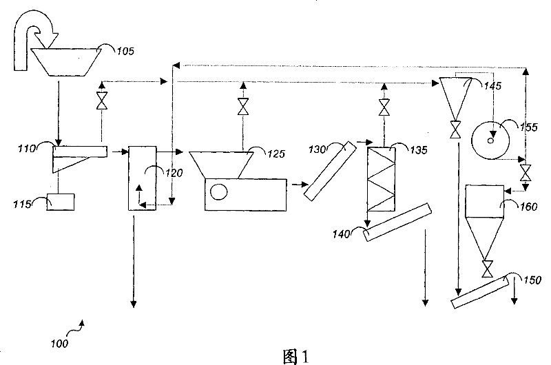
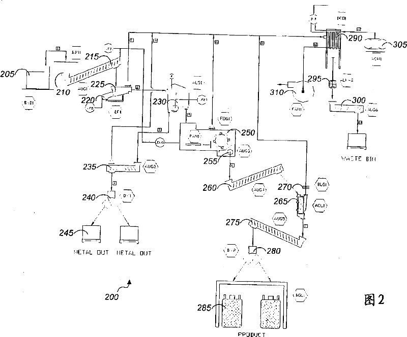
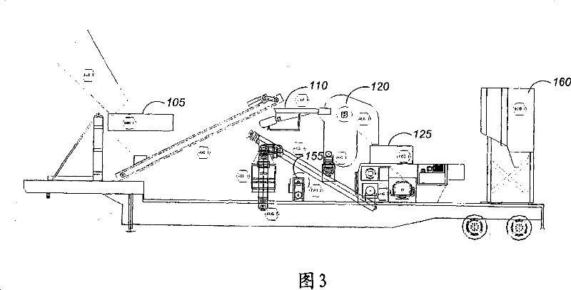

Image

  • Transportable plastics recovery system
  • Transportable plastics recovery system
  • Transportable plastics recovery system

Examples


example 1

[0047] Example 1: Metal removal using an aspirator and grinding system

[0048] Plastic-rich shredded material from printer cartridges and from appliances both contain high levels of metals. The two materials were separated by passing through an air hammer separator manufactured by American International Manufacturing Corporation (Woodland, CA), followed by size reduction in a rotary mill.

[0049] Table 1 shows the percentage of metal rejected in each stream versus the heavy stream of the air hammer separator, and the percentage of total plastic lost in the process. For both material streams, the hammer separator removed most metals with no appreciable loss of plastics.

[0050] Printer Cartridges

example 2

[0051] Example 2: Using suction to remove large pieces of metal

[0052] Coarsely crushed plastic-rich material from the appliance is processed through a pneumatic hammer separator. The separator is tuned to remove nearly all large metal (defined as any size greater than 25mm) that could compromise milling while minimizing loss of plastic.

[0053] Table 2 shows the removal efficiency of large and small pieces of metal. The data show that almost all of the large metals were removed, while only a fraction of the small metals were removed, and very little plastic.

[0054] Percentage of large metals in total metals

example 3

[0055] Example 3: Grinding after pumping to increase bulk density

[0056] Using a pneumatic hammer separator, the coarsely comminuted plastic-rich material from the appliance is first separated into "light" and "heavy" streams. The "light" material was passed through a grinder with a 25.4 mm (one inch) screen.

[0057] Table 3 shows the bulk density of the feed, the "heavy" by-product and the ground "light" product. Bulk density is calculated by weighing the amount of material in the tank and determining the volume by measuring the height of the material filling the tank. In this case the feed does not contain most of the fluff and debris, so it is expected that there will be no bulk density change from the pump down stage of the subsequent milling. The ground "light" product has a higher bulk density than the feed or "heavy" by-product.

[0058] flow

Bulk density (kg / m 3 )

Feed

331

"Heavy" by-products

352

Abrasive "lightweight"...


PUM

PropertyMeasurementUnit
particle sizeaaaaaaaaaa

Abstract

A transportable system for separating materials in a waste stream. An arrangement of separation and grinding devices in mounted on a transportable platform. The devices are configured and arranged to produce three or more product streams from a plastic-rich feed mixture. One of the product streams is a coarse heavy stream, one stream is a ground plastic-rich product stream, and one stream is a ground light material stream. The system can be transported to a waste-goods location, operated to separate waste-goods, and relocated a new location.

Description

[0001] Cross References to Related Applications [0002] This application claims the benefit of US Provisional Application US60 / 397953, filed July 22, 2002, which is hereby incorporated by reference. field of invention [0003] This invention relates to the recycling of plastics, metals and other materials. Background technique [0004] According to "America's Plastics Industry" by the Plastics Industries Association in Washington, D.C., the plastics and related industries are the fourth largest in the United States as they generate more than 36 million metric tons (MT) of materials and $270 billion in products annually, and are responsible for approximately 3.2 million jobs. big industry. However, unlike other materials industries such as steel and aluminum, the industry relies almost entirely on non-renewable raw materials, mainly imported petroleum. This dependence becomes more pronounced as plastics continue to grow faster than all other materials. [0005] Most plast...

Claims


Application Information

Patent Timeline
Patent Type & Authority Applications(China)
IPC IPC(8): B02C21/02B03B9/06B03C7/00B29B17/02B29B17/04B29C48/10B29C48/29B29C48/50
CPCB29B2017/0224B29K2069/00B29K2105/065B29L2030/00B03C7/00B29K2105/0005B29C47/0026B29K2105/0044B29K2105/0032B29K2023/12B29B2017/0094B29C47/0004B29B17/02B29B2017/0265B29B2017/0241B29B2017/0262B29K2077/00B29L2031/767B29K2705/00B29B2017/0279B29C47/1063B29B17/04B29C47/1027B29K2711/12B29K2711/14B03B9/06B29B2017/0268B29K2105/26B29K2055/02B29B2017/0237B29C48/288B29C48/29B29C48/022B29C48/10Y02W30/52Y02W30/62
Inventor P·C·艾伦L·E·艾伦三世
Owner MBA POLYMERS INC
Features
  • R&D
  • Intellectual Property
  • Life Sciences
  • Materials
  • Tech Scout
  • Unparalleled Data Quality
  • Higher Quality Content
  • 60% Fewer Hallucinations
Learn More