Equipment for transporting flexible pipe

A transfer device, tube technology, applied in the direction of conveyor control devices, conveyors, conveyor objects, etc.

Inactive Publication Date: 2007-10-03
天津市普飞特机电技术有限公司
View PDF2 Cites 15 Cited by
  • Summary
  • Abstract
  • Description
  • Claims
  • Application Information

AI Technical Summary

Problems solved by technology

[0005] The problem to be solved by the present invention is to overcome the above-mentioned defects in the conventional technology, and provide a simple structure, without the need for complex mechanical and electrical control equipment, which can detect the lack of tubes in time and replenish them in time, which can accurately and continuously Transfer device for hose tubes for dispensing hose tubes

Method used


Image

  • Equipment for transporting flexible pipe
  • Equipment for transporting flexible pipe
  • Equipment for transporting flexible pipe

Examples


specific Embodiment approach

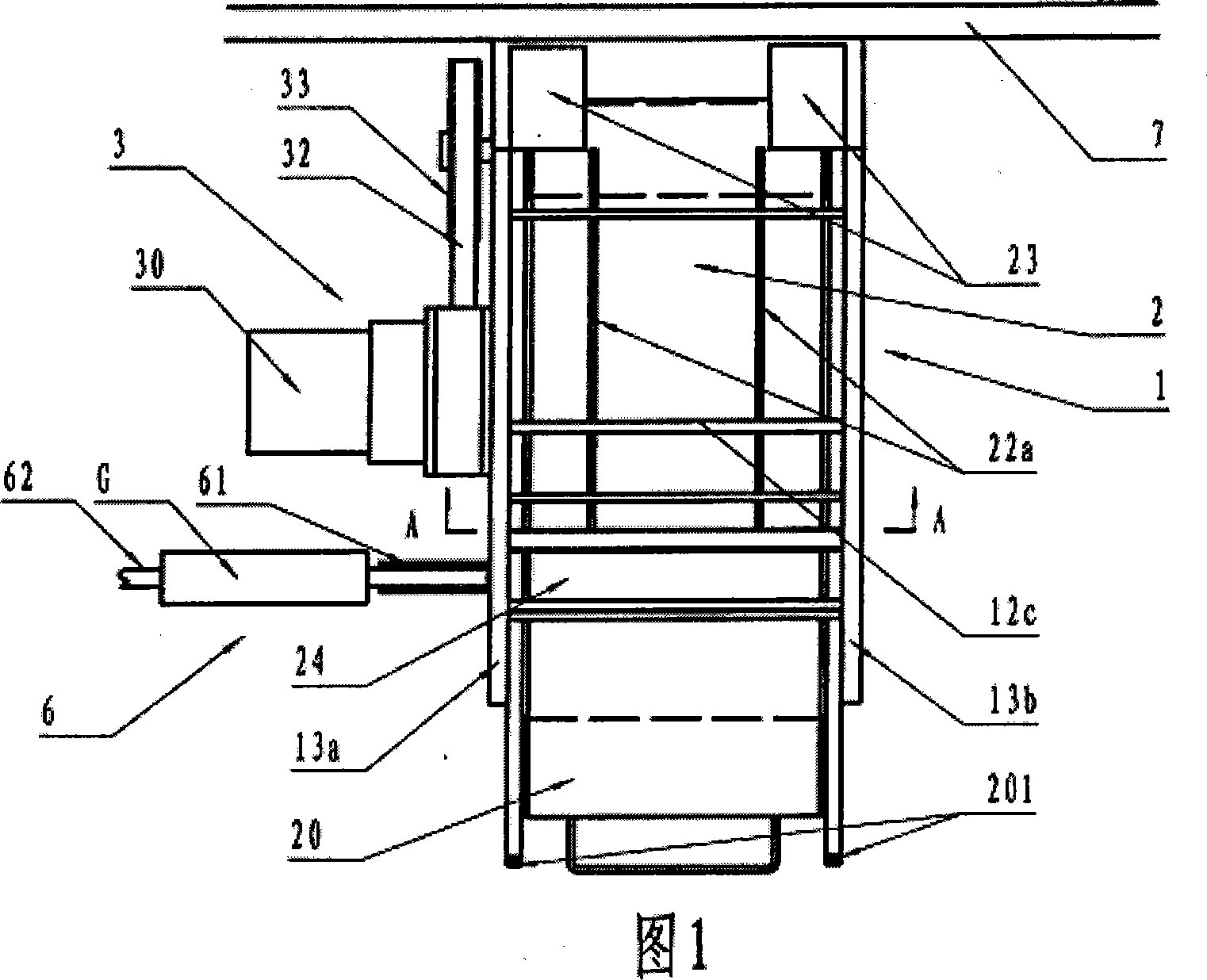
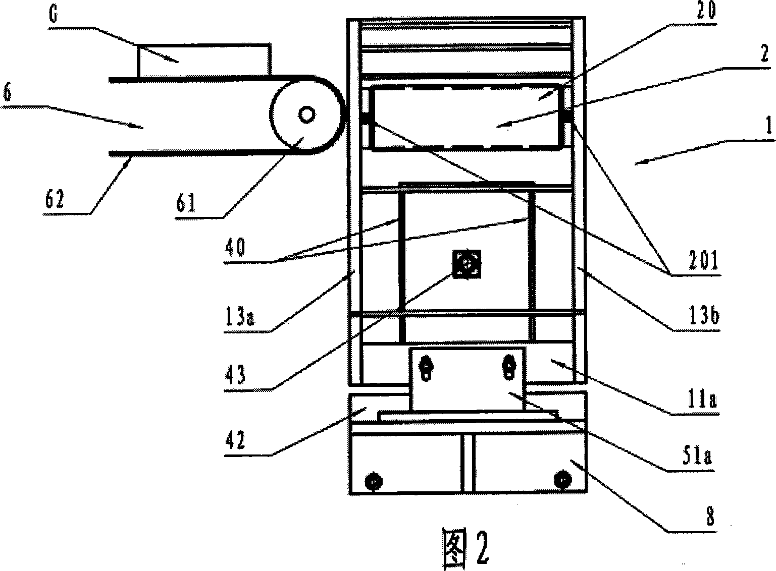
[0024] As shown in Figures 1-4, a hose tube transfer device is installed through the main bracket 8 fixed on the equipment installation base plate 7. The changed tube transfer transmission mechanism 2, which is responsible for receiving the hose tubes fed from the tube linear transmission mechanism 6, for radial transport, wherein,

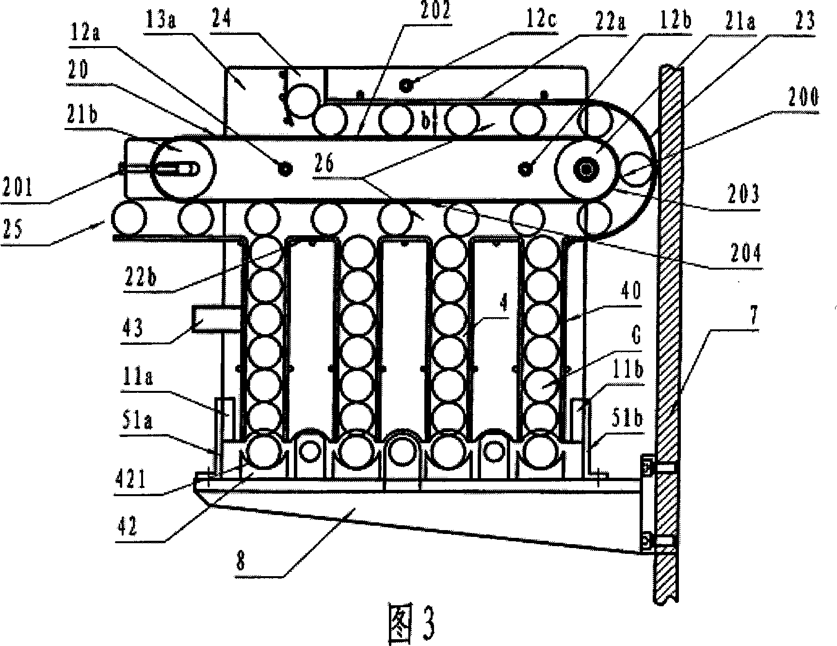
[0025] The tube transfer transmission mechanism 2 is radially arranged relative to the tube linear transmission mechanism 6 arranged in the axial direction, and is installed in the housing 1; The conveyor belt is a radial conveyor belt 20 driven by the driven shaft roller 21b, and the radial conveyor belt 20 is responsible for the radial conveyance of the hose tube;

[0026] The radial conveyor belt is set by the radial conveyor belt driving shaft roller and the radial conveyor belt passive shaft roller, so that the upper surface of the radial conveyor belt can form the first transmission bearing surface between the center shafts of the two shaft ...


PUM


Abstract

A short flexible tube transferring apparatus for transferring the semi-finished flexible tubes to next workstation where the flexible tube is installed to a tube shoulder is composed of a flexible tube transferring unit driven by driver unit and able to change the transfer direction by using the transfer tracks, a flexible tube storage cabin, and a flexible tube locator.

Description

technical field [0001] The invention relates to an assembly equipment for hose components, especially a transfer device for transporting semi-finished hose tubes to the process of fixing them with the shoulder, especially suitable for toothpaste hoses, ointment hoses or other similar composite soft tubes. Pipe assembly equipment. Background technique [0002] Known technology, such as published Chinese patent application 02826482.7 Assembly equipment for pipe parts, relates to an assembly equipment for pipe parts, especially shells with shoulders, comprising the following parts arranged in succession: a shell linearly conveyed machine, a transfer system for changing the direction of the shell by approximately 90°, an assembly device for fixing the shoulder on the shell, wherein the transfer system consists of a grabbing device for the shell and a turning device for the shell, The diverting device consists of a conveyor belt type rotary conveyor p...

Claims


Application Information

Patent Timeline
Patent Type & Authority Applications(China)
IPC IPC(8): B29C65/78B29C31/00B65G15/00B65G47/46B65G47/52B65G47/69B65G43/08B65G23/24B65G23/44
Inventor 李津生李津福李津来
Owner 天津市普飞特机电技术有限公司
Why Eureka
Try Eureka