Vacuum film coating apparatus

A vacuum coating and equipment technology, which is applied in vacuum evaporation coating, sputtering coating, ion implantation coating, etc., can solve the problems of undeveloped, small diameter and length, and no structure of the product, so as to avoid thermal breakdown , avoid electric breakdown, easy to use and flexible effect

Inactive Publication Date: 2007-10-03
MCC CAPITAL ENGINEERING & RESEARCH
View PDF0 Cites 4 Cited by
  • Summary
  • Abstract
  • Description
  • Claims
  • Application Information

AI Technical Summary

Problems solved by technology

For example, the tubular dielectric tube used in the tubular ozone generator has a special shape, small diameter, and long length. There is no coating equipment for such a harsh coating environment. Therefore, the existing vacuum coating equipment Difficult to coat it uniformly
[0004] It can be seen that the above-mentioned existing vacuum coating equipment cannot meet the requirements for the thin and long tubular inner wall coating, so innovation is needed, and further improvement is urgently needed
In order to solve the problems existing in vacuum coating equipment, personnel in related technical fields have not developed suitable design products for a long time, and general products have no suitable structure to solve the above problems. This is obviously a problem that relevant industry players are eager to solve

Method used


Image

  • Vacuum film coating apparatus
  • Vacuum film coating apparatus

Examples


Embodiment Construction

[0039] In order to further explain the technical means and effects of the present invention to achieve the intended purpose of the invention, the specific implementation, structure, characteristics and effects of the vacuum coating equipment proposed according to the present invention will be described below in conjunction with the accompanying drawings and preferred embodiments. Details are as follows.

[0040] Through the description of the specific implementation mode, when the technical means and functions adopted by the present invention to achieve the predetermined purpose can be obtained a deeper and more specific understanding, but the accompanying drawings are only for reference and description, and are not used to explain the present invention be restricted.

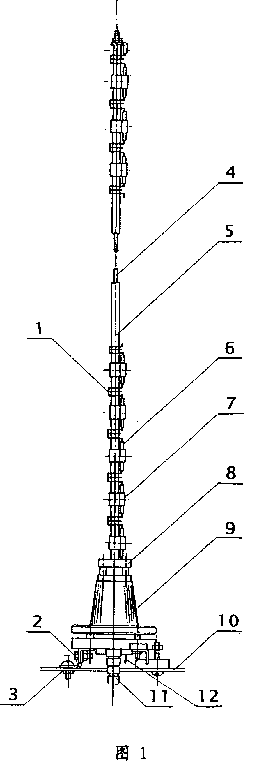
[0041] Please refer to FIG. 1 , which is a schematic structural diagram of a vacuum coating rod according to an embodiment of the present invention. The present invention comprises a vacuum coating rod 1 (as s...


PUM


Abstract

The vacuum film coating apparatus includes one vacuum film coating rod, one film coating seat and one film coating stage. The vacuum film coating rod inserted into the film coating seat on the film coating stage includes one support rod connected to the film coating stage, one insulating casing around the support rod, one evaporating heat source set on the insulating casing and one electric system for heating the coated material on the evaporating heat source. By means of the vacuum film coating rod, the vacuum film coating apparatus can coat film to the inner wall of dielectric tube in lowered film coating cost and has relatively small size.

Description

technical field [0001] The invention relates to a coating device, in particular to a vacuum coating device provided with a vacuum coating rod. Background technique [0002] The existing vacuum coating equipment is to place the solid material in the vacuum chamber. In the high vacuum condition, the selected solid coating material is heated and evaporated at high temperature, and the atoms or molecules produced by the evaporation will be evenly adsorbed to the object to be coated. A thin film forms on the surface. This is a coating process on the exposed surface of the object to be plated suspended in the vacuum chamber in a large vacuum chamber "under large ambient vacuum conditions", and the effective coverage efficiency of the coating material is very small. This type of coating equipment cannot coat the inner wall of the slender tube. [0003] At present, many special vacuum coating occasions require special coating equipment, especially some irregular-shaped coating par...

Claims


Application Information

Patent Timeline
Patent Type & Authority Applications(China)
IPC IPC(8): C23C14/24C23C14/56
Inventor 宋伟民王化民
Owner MCC CAPITAL ENGINEERING & RESEARCH
Why Eureka
Try Eureka