Electrostatic fluid accelerator for and a method of controlling fluid flow

a fluid accelerator and electrostatic technology, applied in the direction of electric supply techniques, instruments, corona discharge, etc., can solve the problems of excessive size requirements of multi-stage efa devices, parasitic current flow between neighboring stages, and inability to generate sparks between electrodes, etc., to achieve the effect of eliminating or significantly reducing stray currents, increasing efa electrode density, and eliminating or reducing stray currents

Inactive Publication Date: 2007-03-01
KRONOS ADVANCED TECH INC
View PDF7 Cites 16 Cited by
  • Summary
  • Abstract
  • Description
  • Claims
  • Application Information

AI Technical Summary

Benefits of technology

[0013] The present invention represents an innovative solution to increase airflow by closely spacing EFA stages while minimizing or avoiding the introduction of undesired effects. The invention implements a combination of electrode geometry, mutual location and the electric voltage applied to the electrodes to provide enhanced performance.
[0016] The present invention increases EFA electrode density (typically measured in stages-per-unit-length) and eliminates or significantly decreases stray currents between the electrodes. At the same time, the invention eliminates corona discharge between electrodes of neighboring stages (e.g., back corona). This is accomplished, in part, by powering neighboring EFA stages with substantially the same voltage waveform, i.e., the potentials on the neighboring electrodes have the same or very similar alternating components so as to eliminate or reduce any a.c. differential voltage between stages and minimize an instantaneous voltage differential between immediately adjacent electrodes of adjacent stages. Operating in such a synchronous manner between stages, electrical potential differences between neighboring electrodes of adjacent EFA components remains constant and any resultant stray current from one electrode to another is minimized or completely avoided. Synchronization may be implemented by different means, but most easily by powering neighboring EFA components with respective synchronous and synphased voltages from corresponding power supplies, or with power supplies synchronized to provide similar amplitude a.c. components of the respective applied voltages. This may be achieved with the same power supply connected to neighboring EFA components or with different, preferably matched power supplies that produce synchronous and syn-phased a.c. component of the applied voltage. A further increase in the density of the electrodes (i.e., “electrode density”) may be achieved by placing neighboring (i.e., immediately adjacent) stages with opposite polarity of the corona and collecting electrodes, i.e. the closest to each other electrodes of the neighboring stages having the same or similar (i.e., “close”) electrical potentials.

Problems solved by technology

One of these deficiencies includes excessive size requirements for multi-stage EFA devices since several stages of EFA, placed in succession, require substantial length along an air duct (i.e., along air flow direction).
Still other problems arise when stages are placed close to each.
Moreover, due to the electrical capacitance between the neighboring stages, there is a parasitic current flow between neighboring stages.
Still another problem develops using large or multiple stages so that each separate (or groups of) stage(s) is provided with its own high voltage power supply (HVPS).
In this case, the high voltage required to create the corona discharge may lead to an unacceptable level of sparks being generated between the electrodes.
That leads to an undesirable increase in power interruption for the system as a whole.

Method used


Image

  • Electrostatic fluid accelerator for and a method of controlling fluid flow
  • Electrostatic fluid accelerator for and a method of controlling fluid flow
  • Electrostatic fluid accelerator for and a method of controlling fluid flow

Examples


Embodiment Construction

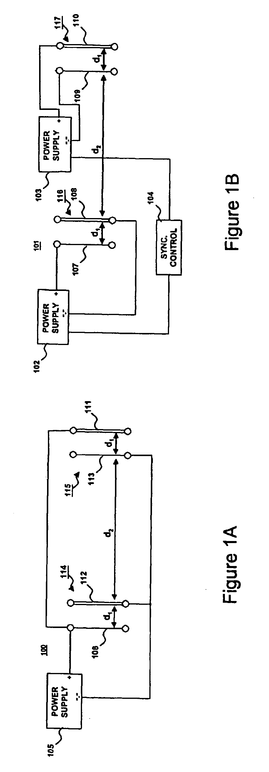
[0027]FIG. 1A is a schematic diagram of an Electrostatic Fluid Accelerator (EFA) device 100 comprising two EFA stages 114 and 115. First EFA stage 114 includes corona discharge electrode 106 and associated accelerating electrode 112; second EFA stage 115 includes corona discharge electrode 113 and associated accelerating electrode 111. Both EFA stages and all the electrodes are shown schematically. Only one set of corona discharge and collecting electrodes are shown per stage for ease of illustration, although it is expected that each stage may include a large number of arrayed pairs of corona and accelerating electrodes. An important feature of EFA 100 is that the distance d1 between the corona discharge electrode 106 and collector electrode 112 is comparable to the distance d2 between collector electrode 112 and the corona discharge electrode 113 of the subsequent stage 115, i.e., the closest distance between elements of adjacent stages is not much greater than the distance betwee...


PUM


Abstract

An electrostatic fluid acceleration and method of operation thereof includes at least two synchronously powered stages with final or rear-most electrodes of one stage maintained at substantially the same instantaneous voltage as the immediately adjacent initial or forward-most electrodes of a next stage in an airflow direction. A single power supply or synchronized and phase controlled power supplies provide high voltage power to each of the stages such that both the phase and amplitude of the electric power applied to the corresponding electrodes are aligned in time. The frequency and phase control allows neighboring stages to be closely spaced at a distance of from 1 to 2 times an inter-electrode distance within a stage, and, in any case, minimizing or avoiding production of a back corona current from a corona discharge electrode of one stage to an electrode of a neighboring stage. Corona discharge electrodes of neighboring stages may be horizontally aligned, complementary collector electrodes of all stages being similarly horizontally aligned between and horizontally offset from the corona discharge electrodes.

Description

RELATED APPLICATIONS [0001] This application is a continuation-in-part of U.S. patent application Ser. No. 10 / 188,069 filed Jul. 3, 2002 and entitled Electrostatic Fluid Accelerator For And A Method Of Controlling Fluid Flow and the continuation thereof, U.S. patent application Ser. No. 10 / 806,473 filed Mar. 23, 2004 of the same title, and is related to and U.S. patent application Ser. No. 09 / 419,720 filed Oct. 14, 1999 and entitled Electrostatic Fluid Accelerator, now U.S. Pat. No. 6,504,308, U.S. patent application Ser. No. 10 / 175,947 filed Jun. 21, 2002 and entitled Method of and Apparatus for Electrostatic Fluid Acceleration Control of a Fluid Flow, now U.S. Pat. No. 6,664,741; U.S. patent application Ser. No. 10 / 187,983 filed Jul. 3, 2002 and entitled Spark Management Method And Device; U.S. patent application Ser. No. 10 / 295,869 filed Nov. 18, 2002 and entitled Electrostatic Fluid Accelerator which is a continuation of U.S. provisional application Ser. No. 60 / 104,573, filed on...

Claims


Application Information

Patent Timeline
Patent Type & Authority Applications(United States)
IPC IPC(8): H05H7/00B03C3/017B03C3/08B03C3/36B03C3/68H01J23/00H05H1/24
CPCB03C3/017B03C3/08B03C3/12B03C3/368H05H1/24B03C3/68B03C2201/04B03C2201/14B03C3/41H05H5/00H05H1/47
Inventor KRICHTAFOVITCH, IGOR A.GOROBETS, VLADIMIR L.
Owner KRONOS ADVANCED TECH INC
Why Eureka
Try Eureka