Magnetron

A technology of magnetron and anode tube, which is applied in the field of magnetron, can solve the problems of excess electrons, failure to pay attention to the relationship of peak anode current value, and no noise reduction effect, etc., to achieve the effect of suppressing attenuation and reducing noise

Inactive Publication Date: 2007-10-03
PANASONIC CORP
View PDF1 Cites 11 Cited by
  • Summary
  • Abstract
  • Description
  • Claims
  • Application Information

AI Technical Summary

Problems solved by technology

[0016] Although the effect of reducing noise below 1 MHz is described in the technology given in Patent Document 2, no attention is paid to the relationship with the peak anode current value
As shown in FIG. 38 , it was also confirmed by experiments conducted by the inventors of the present application on the basis of the technology disclosed in Patent Document 2 that the noise reduction effec

Method used


Image

  • Magnetron
  • Magnetron
  • Magnetron

Examples


Embodiment 1

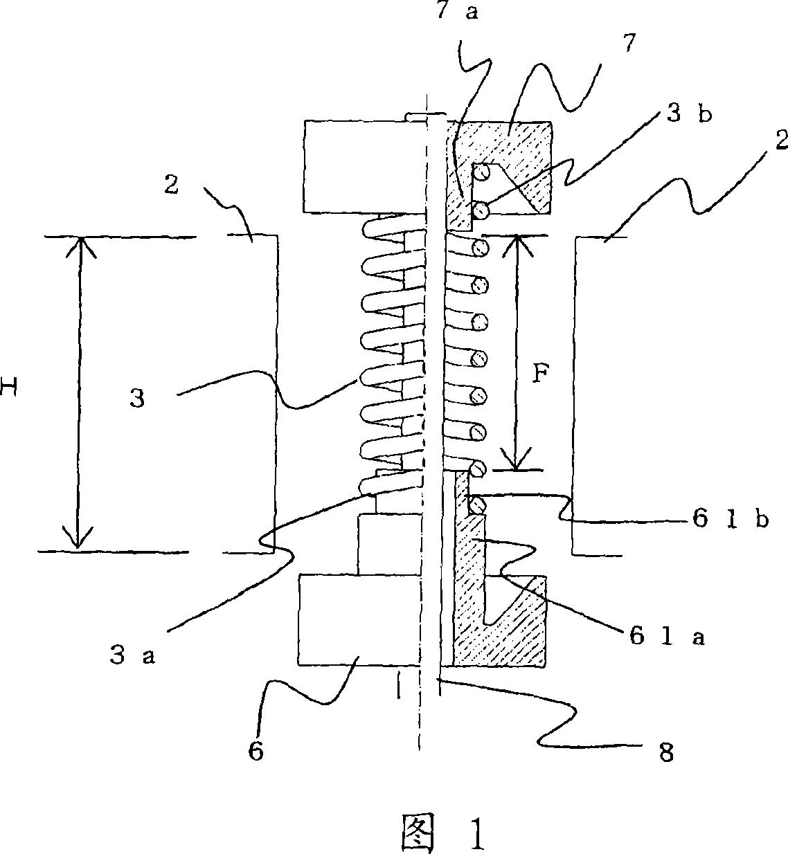
[0099] 1 is a partial longitudinal sectional view of a cathode portion of a magnetron according to Embodiment 1 of the present invention. In addition, since components other than the cathode shown in this figure are the same as those of the conventional magnetron shown in FIG. 32 described above, their descriptions are omitted.

[0100] Referring to FIG. 1 , the magnetron of this embodiment is configured so that the spiral filament 3 is disposed between the input side end cap 61 and the output side end cap 7 supported by the cathode support rod 8 . In particular, in the present embodiment, the input side end cap 61 is configured so that the sleeve 61a having a larger diameter extends toward the inside of the interaction space compared with the shape in FIG. 32 , and the sleeve 61b having a smaller diameter and the end 3a of the filament 3 are fixed to each other. The output-side end cap 7 has the same shape as a conventional end cap, and the sleeve 7 a and the end 3 b of the ...

Embodiment 2

[0109] Fig. 6 is a partial longitudinal sectional view of a cathode portion of a magnetron according to Embodiment 2 of the present invention. In addition, since components other than the cathode shown in this figure are the same as those of the conventional magnetron shown in FIG. 32 described above, their descriptions are omitted.

[0110] In FIG. 6, the magnetron of this embodiment is configured so that the cathode of the above-mentioned Embodiment 1 shown in FIG. 1 is reversed, and the electron-emitting portion is shifted toward the input side.

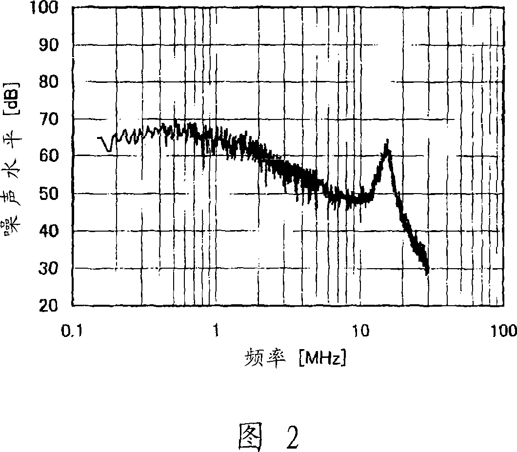
[0111] 7 is a waveform diagram showing a noise level of 30 MHz or less when the size of the electron emission portion of the present embodiment is set to about 75% of the axial dimension of the plate blade and the electron emission portion is shifted to the input side.

[0112] Even if the electron emission portion is shifted toward the input side like this embodiment, the noise level of 30 MHz or below is suppressed as compared w...

Embodiment 3

[0115] Fig. 8 is a partial longitudinal sectional view of a cathode portion of a magnetron according to Embodiment 3 of the present invention. In addition, since components other than the cathode shown in this figure are the same as those of the conventional magnetron shown in FIG. 32 described above, their descriptions are omitted.

[0116] In FIG. 8 , the magnetron of the present embodiment is configured such that the electron emission portion is configured to extend into the recess 72 a of the output-side end cap 72 . This embodiment is described with reference to the drawings, and the input side end cap 61 has the same structure as that of Embodiment 1 shown in FIG. 1 . The output side end cap shown in FIG. 1 is configured such that the shaft sleeve 7a of the output side end cap 7 and the inner diameter portion of the end portion 3b of the filament 3 are fixed to each other, while the output side end cap 72 shown in FIG. 8 is formed as an output side end cap 72. The inner...


PUM

PropertyMeasurementUnit
Wire diameteraaaaaaaaaa
Pitchaaaaaaaaaa

Abstract

To provide a magnetron capable of reducing noises in a low frequency band of 30 MHz or less without deteriorating the stability of a load depending on phases, and also ensuring the precision of assembly dimensions without increasing the number of components, a coiled filament 3 is arranged between an input-side end hat 61 and an output-side end hat 7 which are supported by a cathode supporting rod 8. A larger-diameter boss 61 a in the end hat 61 extends to the interior of an interaction space, a smaller-diameter boss 61 b and one end 3a of the filament 3 are secured to each other, and the other end 3b is secured to a boss 7a of the end hat 7. Here, the dimension of an axial free length part F which forms an electron emission part which is not secured to the end hats 61 and 7 of the filament 3 is set to 50% or more and 80% or less of the axial dimension H of plate-like vanes 2, and the electron emission part is arranged so as to be displaced to the output side.

Description

technical field [0001] The present invention relates to a magnetron used in a high-frequency device whose noise is intended to be reduced. Background technique [0002] A conventional magnetron will be explained below with reference to the drawings. [0003] Fig. 32 is a longitudinal sectional view showing an interaction space where electrons of a magnetron move in a conventional device. In this magnetron, a plurality of plate blades 2 (only two blades are shown in this figure) are arranged radially inside the anode tube 1, and the plate blades 2 pass through pressure equalizing rings 9, 10, 11 and 12 Connect alternately. By connecting the grading rings 9, 10, 11 and 12 alternately in this way, the magnetron will oscillate stably in the mode. Meanwhile, a cathode 13 constituted by a spiral filament 3 , a pair of end caps 6 and 7 , and a cathode support rod 8 is provided along the central axis of the anode tube 1 . The filament 3 is made of tungsten containing 1-2% thoriu...

Claims


Application Information

Patent Timeline
IPC IPC(8): H01J25/50H01J23/02H01J23/04
Inventor 桑原渚石井健相贺正幸
Owner PANASONIC CORP
Why Eureka
Try Eureka