Vertebral arch positioning stent for cervical vertebra spinal canal enlargement operation

A technology of positioning frame and spinal canal is applied in the field of vertebral arch positioning frame used for spinal canal enlargement of cervical vertebral body, which can solve the problems of easy deformation of skeleton or device, increased inventory burden, and no development, etc. Inventory burden, reduced time, fully combined effect

Inactive Publication Date: 2007-10-10
BIOALPHA CORP
View PDF6 Cites 12 Cited by
  • Summary
  • Abstract
  • Description
  • Claims
  • Application Information

AI Technical Summary

Problems solved by technology

Therefore, if the fixation accuracy of the frame or device is reduced, the dilated spinal canal will contract again and reproduce the symptoms, and the inventory burden will increase because the manufacturing company must equip products with various sizes and angles
[0015] In order to solve the above problems, the skeleton or device for spinal canal enlargement must be easily deformed, however, no material has been developed that has the property of being easily deformable while being directly bonded to the bone

Method used


Image

  • Vertebral arch positioning stent for cervical vertebra spinal canal enlargement operation
  • Vertebral arch positioning stent for cervical vertebra spinal canal enlargement operation
  • Vertebral arch positioning stent for cervical vertebra spinal canal enlargement operation

Examples


Embodiment Construction

[0041] Hereinafter, preferred embodiments of the present invention will be described in detail with reference to the accompanying drawings.

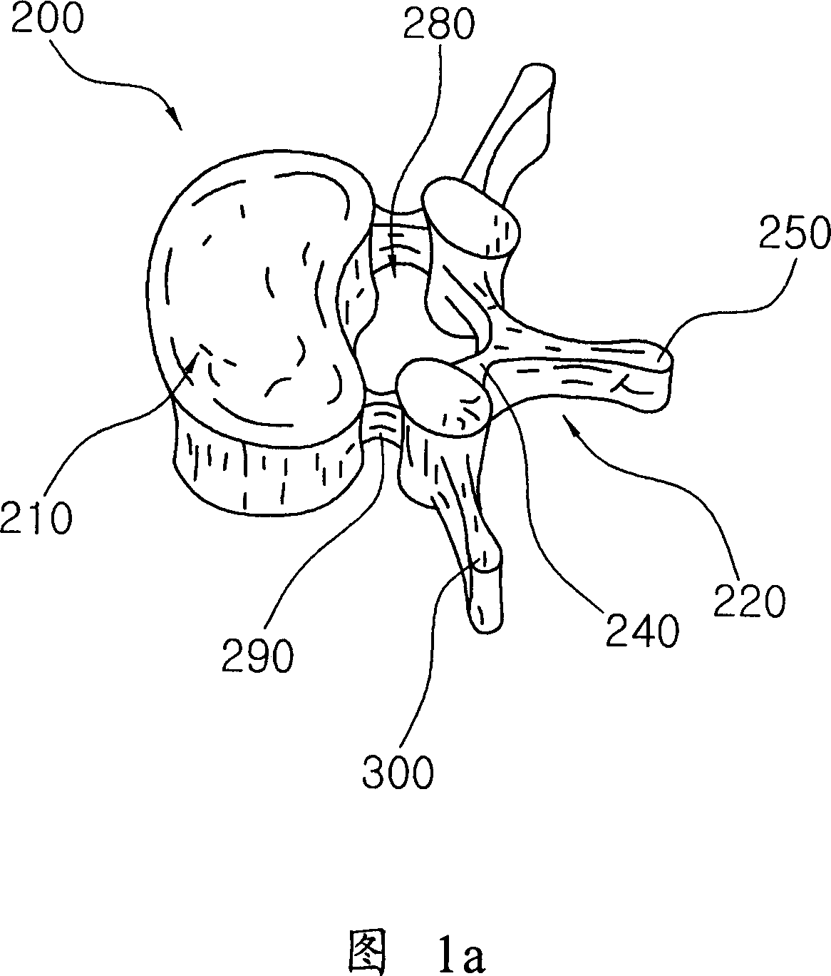
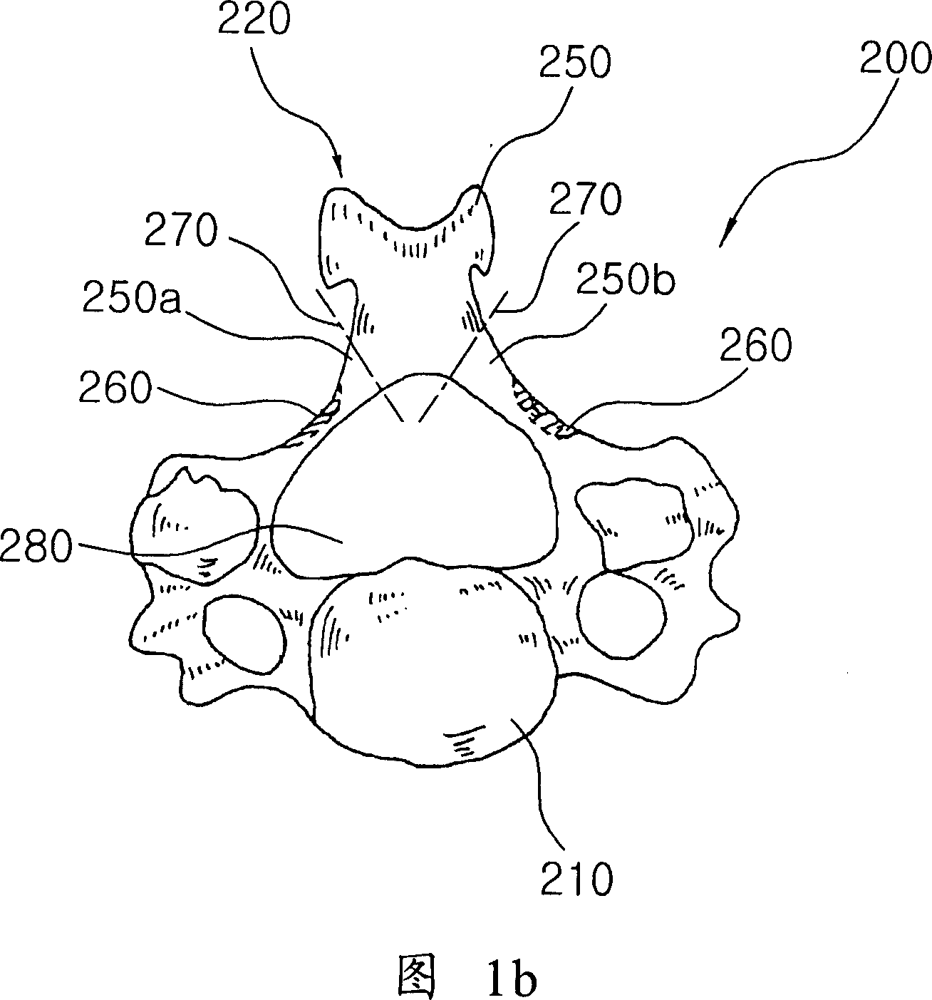
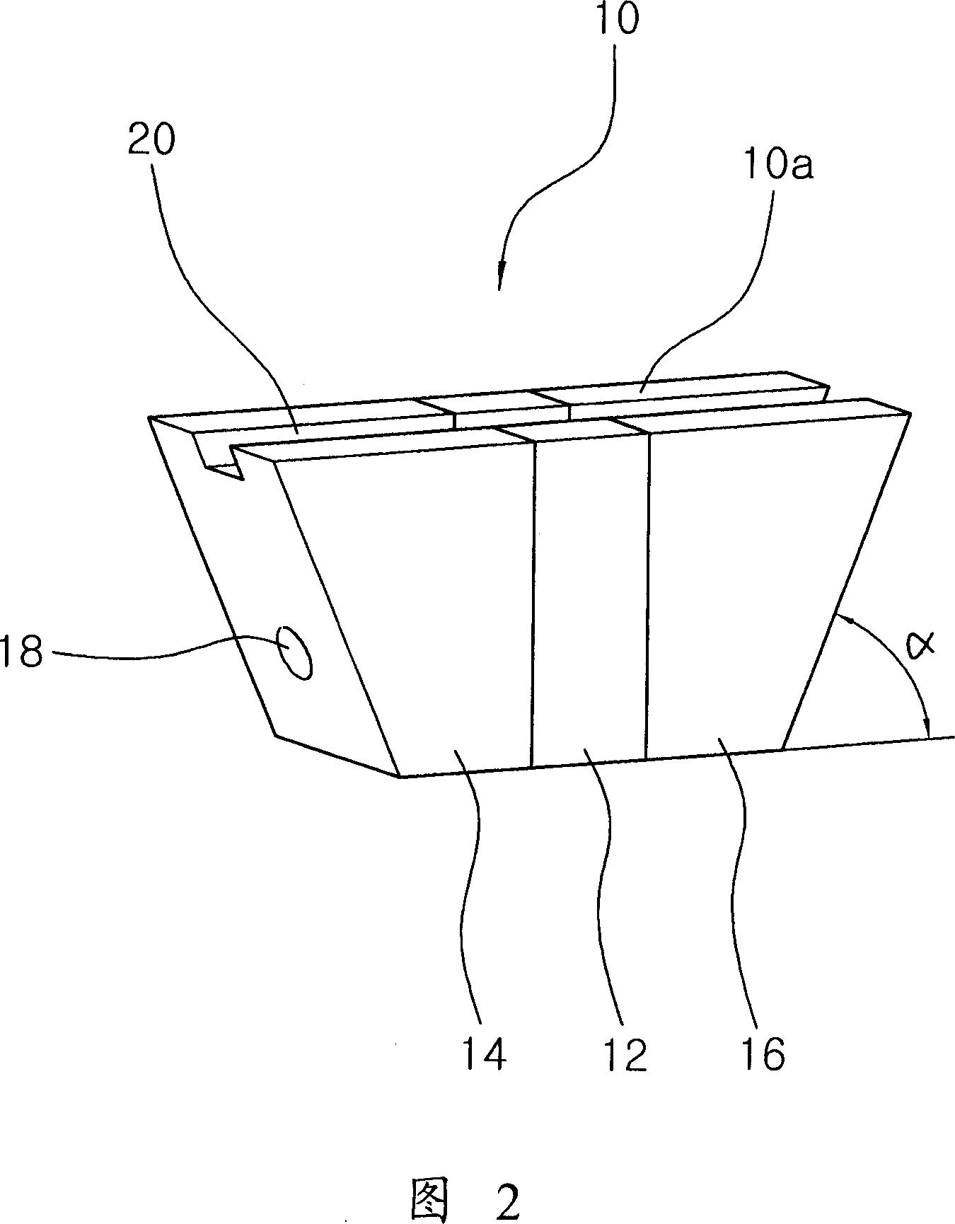
[0042] Fig. 1a and Fig. 1b are a perspective view of a typical vertebral structure and an explanatory diagram for explaining a spinal canal enlargement operation of dividing a cervical vertebral body by a center line, respectively. Fig. 2 is a perspective view of the vertebral arch positioning frame used in the spinal canal enlargement operation of the cervical vertebrae according to the present invention. Fig. 6 is an explanatory view for explaining the enlargement of the spinal canal by using the vertebral arch positioning frame of the present invention to perform central line division of the cervical vertebral body.

[0043] First, a spinal canal enlargement operation in which the cervical vertebral body is divided by the centerline will be briefly described using FIG. 1a and FIG. 1b.

[0044] FIG. 1 a shows a perspective view of a t...


PUM


Abstract

The present invention provides a vertebral arch orientation frame using for vertebral canal enlargement operation of the cervical vertebra body. The orientation frame includes springy deformation part which is setted in the middle and is composed of material with excellent spring. The first and the second combination part which connect to the two end of the given springy deformation part separately and combine with the dissected post-arch surface of the cervical vertebra body. This invention plays the articular function through the given springy deformation part, there is setted a pair of bone conductivity combination part composing of biological activity ceramic which can combine with the bone directly on the two end of the springy deformation part. The bone conductivity combination part can deform corresponding with the dissected post-arch surface mode with various angle and size when the post-arch of the cervical vertebra body forming so as to possess the larger contacting area with the dissected post-arch and implement combination completely.

Description

technical field [0001] The present invention relates to a vertebral arch positioning frame for cervical spinal canal enlargement, in particular to the following vertebral arch positioning frame for cervical spinal canal enlargement, the middle part is formed of a material with excellent elasticity to form a joint , the other part is constructed of bioactive ceramics including hydroxyapatite that has direct bone bonding properties, allowing it to deform to fit a variety of angles and sizes and allow full bonding at the bone-contacting part. Background technique [0002] Cervical spine (neck bone) stenosis, ossification of the posterior longitudinal ligament, and spondylotic myelopathy, which occur frequently in the elderly and men aged 50 to 60, are caused by the development of the spine. A disease in which the arms and legs become paralyzed when the compression on the spinal cord becomes severe. This disease often occurs in oriental people. For treatment, anterior decompres...

Claims


Application Information

Patent Timeline
Patent Type & Authority Applications(China)
IPC IPC(8): A61B17/56A61B17/70A61F2/44
CPCA61B17/7071A61B17/70
Inventor 柳昡丞洪国善郑圣守张凤淳李春基
Owner BIOALPHA CORP
Why Eureka
Try Eureka