Movable type forming machine for U type trench wall

A mobile and forming machine technology, which is applied in the direction of ceramic forming machines, ceramic extrusion dies, manufacturing tools, etc., can solve the problems of weak structure, high cost and easy damage of the canal wall, and achieve simple structure, resource saving, cleverly conceived effects

Inactive Publication Date: 2007-10-10
刘西军
View PDF0 Cites 4 Cited by
  • Summary
  • Abstract
  • Description
  • Claims
  • Application Information

AI Technical Summary

Problems solved by technology

[0002] At present, the walls of canals for farmland irrigation need to be built with traditional bricks and cement. It is not only labor-intensive and t

Method used


Image

  • Movable type forming machine for U type trench wall
  • Movable type forming machine for U type trench wall

Examples


Embodiment Construction

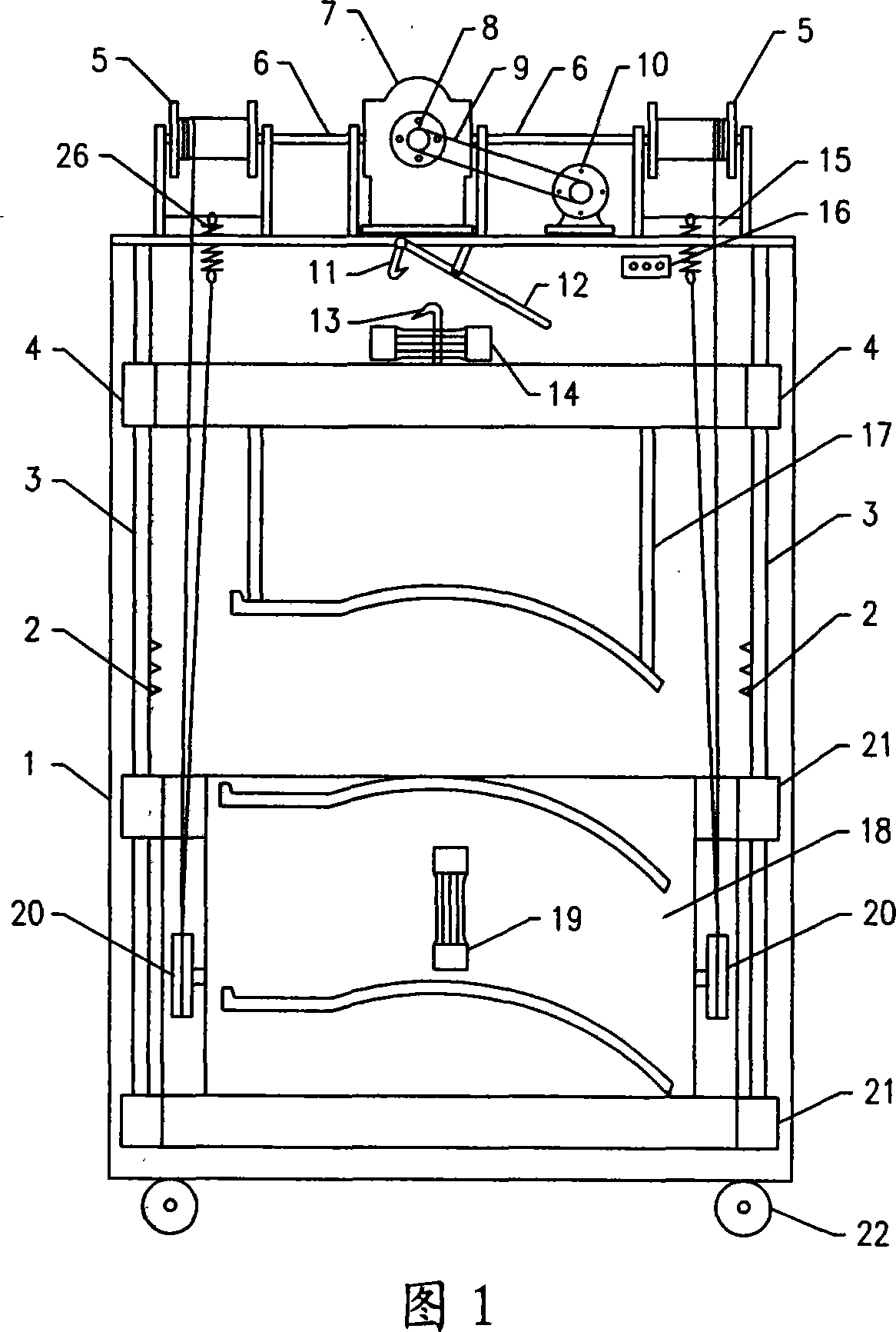
[0009] Among Fig. 1, the upper end of frame 1 is provided with motor 10, and the left end of motor is equipped with reduction box 7, and the left and right two outsides of reduction box are provided with winch 5, and the lower side of winch is equipped with lifting spring 26, and the inboard of winch is provided with connection. A shaft joint, the left and right ends of the reduction box are provided with a drive shaft, the drive shaft is respectively equipped with a connecting shaft 6, and the two ends of the connecting shaft 6 are respectively installed and connected to the connecting shaft head of the hoist. The front end of reduction box is provided with belt pulley 8, and drive pulley is housed on the motor, and drive belt 9 is housed on reduction box pulley and motor drive pulley. The left and right sides of the frame are equipped with guide shafts 3, and the frame on the lower side of the reduction box is provided with an upper mold 17 and a lower mold 18. The upper mold...


PUM


Abstract

A movable forming machine for the U-shaped canal wall is composed of machine frame, motor with speed reducer, left and right winders, lower die with U-shaped moulding cavity, upper die with punch die plate, lifting pulleys for lower die, steel cables for said pulley and winder, and two vibrators respectively for upper and lower dies.

Description

Technical field: [0001] The invention relates to a farmland water conservancy machine, specifically a mold forming machine for processing and producing water canal walls. Background technique: [0002] At present, the walls of canals for farmland irrigation need to be built with traditional bricks and cement. It is not only labor-intensive and time-consuming, but also extremely expensive. Moreover, the structural strength of the canal walls is not strong, and they are easily damaged during use. . Invention content: [0003] The purpose of the present invention is to provide a mobile U-shaped canal wall forming machine, which preforms the canal wall and installs it at one time during use, eliminating the need for on-site construction in the canal bottom, high labor intensity and loose and weak canal wall structure, which is easy to damage high defect. [0004] The scheme of the present invention is composed of a frame, a motor, a reduction box, a hoist, an upper mold, a l...

Claims


Application Information

Patent Timeline
IPC IPC(8): B28B3/26B28B1/087
Inventor 刘西军
Owner 刘西军
Why Eureka
Try Eureka