Method and device for designing linear laser three dimension scanner

A laser three-dimensional and scanner technology, applied in the direction of optical devices, measuring devices, optics, etc., can solve the problems of inaccurate positioning of imaging positions, difficulty in ensuring accurate values ​​of optical geometric parameters, difficulty in reflecting CCD resolution and depth of focus, etc.

Inactive Publication Date: 2007-10-10
天津智通信息系统集成有限公司
View PDF0 Cites 1 Cited by
  • Summary
  • Abstract
  • Description
  • Claims
  • Application Information

AI Technical Summary

Problems solved by technology

[0007] From the above description, it can be seen that it is difficult to guarantee the exact values ​​of all optical geometric parameters, such as the position of the optical center of the lens, the exact position of the CCD imaging...

Method used


Image

  • Method and device for designing linear laser three dimension scanner
  • Method and device for designing linear laser three dimension scanner

Examples


Embodiment Construction

[0013] The present invention will be described in detail below in conjunction with the accompanying drawings and embodiments.

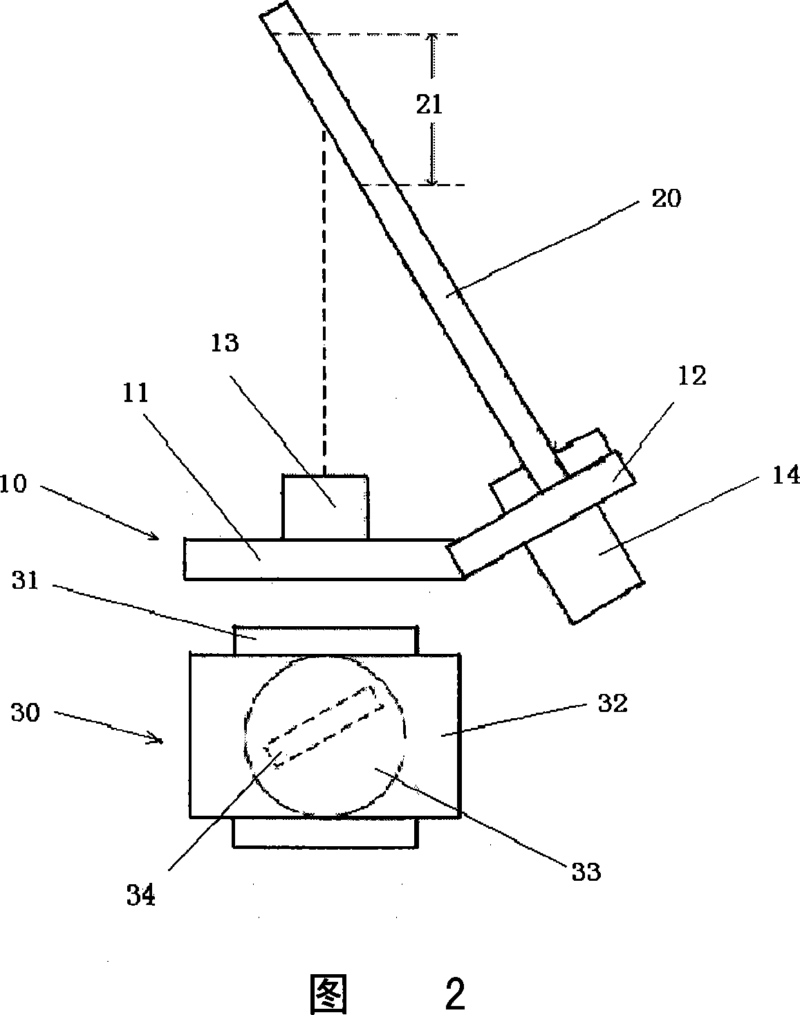
[0014] As shown in Figure 2, the device of the present invention includes a lens-laser bracket 10, a laser exit surface plate 20 and an imaging device micro-movement platform 30, and the plane 11 and the bending surface 12 on the lens-laser bracket 10 are based on the final product The parameters are precisely designed and processed as a part. An optical lens 13 is arranged on the lens-laser plane 11 , and a laser emitting surface plate 20 is arranged on the bending surface 12 , and a mark of a measuring range 21 is arranged on the laser emitting surface plate 20 . The imaging device micro-motion platform 30 is a three-dimensional motion platform purchased on the market, which includes a left and right micro-motion platform 31, a front and rear micro-motion platform 32, and a rotation micro-motion platform 33. An imaging device 34 is arranged in the h...


PUM


Abstract

A method for designing linear laser 3-D scanner includes designing support according included angle between lens optical axis direction and laser beam outgoing plane, firm-jointing a laser beam outgoing flat plate to replace laser beam outgoing plane to mark optimum imaging position and measurement range on said flat plate, using a imaging device micro-move platform under support to accurately measure out included angle between imaging device and optical lens and distance data between imaging device and center of optical lens for confirming design parameter of said scanner.

Description

technical field [0001] The present invention relates to a device for designing a scanner, in particular to a method and device for designing a line laser three-dimensional scanner based on the principle of triangulation. Background technique [0002] The design and production process of the line laser three-dimensional scanner based on the triangulation method is mainly based on the theoretical calculation of the performance index of the scanner, and the parameters and structural parameters of the main components of the scanner are initially selected. Some use optical simulation software for simulation experiments, such as ZEMAX software, to determine whether the requirements are reasonable, whether the selected component parameters meet the requirements of the scanner, whether there is interference in the installation space, etc. [0003] As shown in Figure 1, the parameters to be obtained by the scanner include: 1, the lens focal length f; 2, the angle θ between the optica...

Claims


Application Information

Patent Timeline
IPC IPC(8): G01B11/00G01C3/00G01C9/00G02B26/10
Inventor 汤青韦巍侯晓萍代亮谭贤顺宋晓斌
Owner 天津智通信息系统集成有限公司
Why Eureka
Try Eureka