


Quick Research
Generate reliable direction feasibility study reports for your R&D in just a few steps.

Technical Q&A
Discover and master advanced knowledge NOW. Basics, ideas, possibilities, all at once.

Find Solutions
As an expert in R&D theories, this can generate solutions to your technical problems instantly.

Evaluate Feasibility
Analyze your overall solution with one click, know your potential R&D risks in advance.

Monitor Landscape
Get weekly tech updates, stay abreast of the latest tech innovations and key insights.
Suspension, and head gimbal assembly and disk drive using the same
一种悬臂件、磁头的技术,应用在臂部件的结构、臂和臂架之间的电连接、换能头相对于臂部件的安装/连接等方向,能够解决降低挠性件103、降低磁盘驱动器可靠性、无法进行磁盘驱动器迅速启动等问题,达到提高线性刚度的效果
- Summary
- Abstract
- Description
- Claims
- Application Information
AI Technical Summary
Problems solved by technology
Method used
Image

Examples
Embodiment 1
[0057] The first embodiment of the present invention will be described with reference to FIG. 4 to FIG. 8 . 4 to 5 show the structure of the head gimbal assembly of the present invention, and FIGS. 6 to 7 are enlarged schematic views showing the structure of the flexure and wiring. Fig. 8 is data showing the characteristics of the flexible member of this embodiment.
[0058] [constitute]
[0059] 4 to 5 show a structural example of the HGA 10 mounted on the hard disk drive related to this embodiment. FIG. 4 shows a side view, and FIG. 5 shows a top view of FIG. 4 viewed from below (the surface facing the magnetic disk).
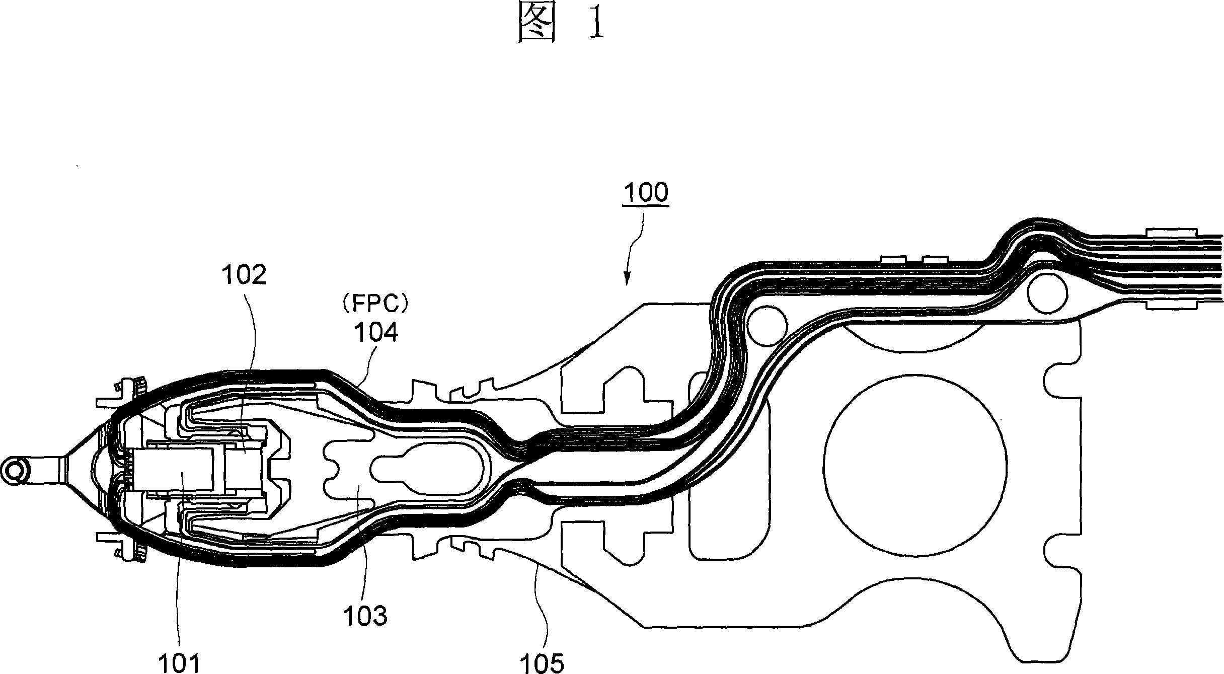
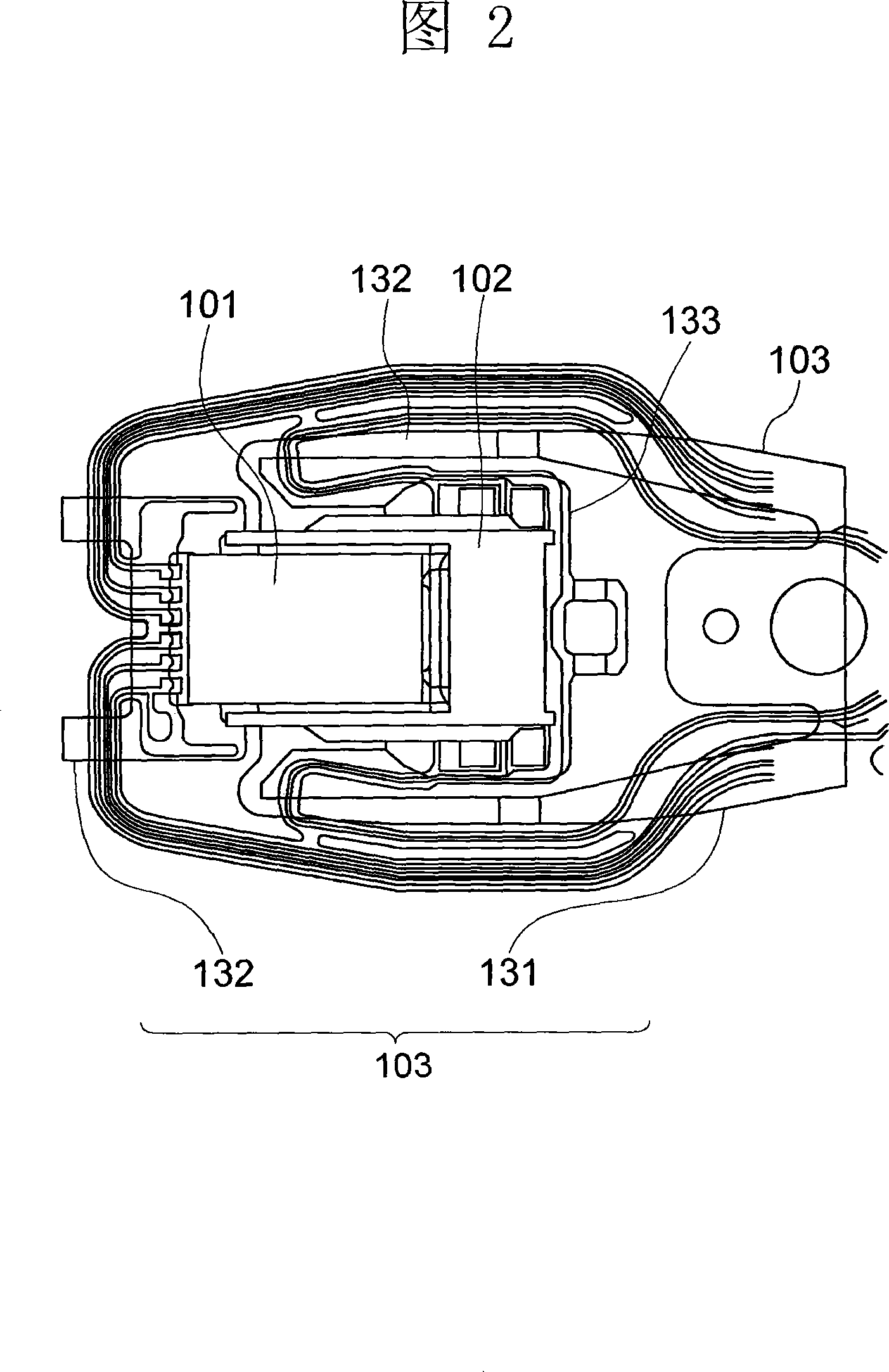
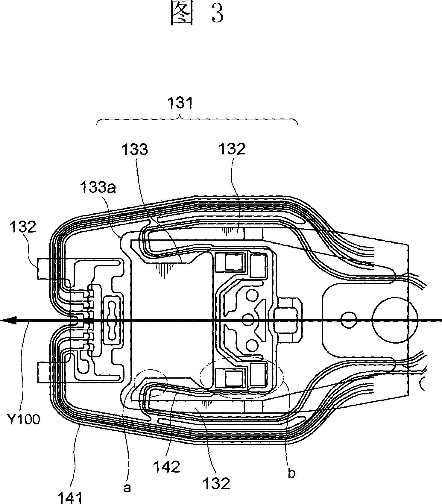
[0060] As shown in Fig. 4 and Fig. 5, the magnetic head gimbal assembly 10 includes: a magnetic head slider 1; a micro-actuator 2 that micro-drives the magnetic head slider 1 and is clamped by an arm; A microactuator 2 and an elastic flexible member 3; a wiring 4 (FPC (flexible printed circuit)) that is formed on the flexible member 3 and transmits signals...
Embodiment 2
[0073] Next, in the cantilever members 3 and 4 of the above structure, the simulation performed to investigate the appropriate value by changing the position and area of the adhesive portion A (fixed portion between the flexible member 3 and the wiring 4 ) will be described. result.
[0074] First, description will be made with reference to FIG. 9A to FIG. 12 . 9A, 9B, 10A, and 10B show suspension members 3 and 4 of different shapes designed by changing the bonding area between the wiring 4 (actuator lead 42 ) on the bonding portion A and the tongue portion 33 . In addition, for convenience of explanation, the structure shown in FIG. 9A is called model 1, and the structure shown in FIG. 10A is called model 3. Each of FIGS. 9A and 10A shows a plan view, and each of FIGS. Schematic enlarged view of site α. In addition, although the simulation was performed using the model 2 and the model 4 having different shapes, the relevant illustration of the other model 2 and the model ...
Embodiment 3
[0086] Next, a third embodiment of the present invention will be described with reference to FIGS. 21 to 22 . In the above-mentioned embodiment, the case where the microactuator is mounted on the HGA and the actuator wire 42 connected to the microactuator is connected to the tongue part 33 has been described. However, in this embodiment, the wiring 4 connected to the read element side terminal formed on the end surface of the magnetic head slider (not shown) is bonded (fixed) to the tongue portion 33 .
[0087] Fig. 21 shows one example. In this illustration, the wiring 4 extending from the rear end side of the flexible member 3 to the cantilever beam 32 facing the reading element side terminal located at the front end is bent inwardly in front of the front end, and a part of the bent portion 42a is It is adhered (fixed) on the inner side of the tongue part 33 . Also, the wiring 4 extends toward the front end side, is bent back toward the tongue portion 33 in front of the co...
PUM
 Abstract
Description
Claims
Application Information
 - R&D Engineer
- R&D Manager
- IP Professional
- Industry Leading Data Capabilities
- Powerful AI technology
- Patent DNA Extraction
Browse by: Latest US Patents, China's latest patents, Technical Efficacy Thesaurus, Application Domain, Technology Topic, Popular Technical Reports.
© 2024 PatSnap. All rights reserved.Legal|Privacy policy|Modern Slavery Act Transparency Statement|Sitemap|About US| Contact US: help@patsnap.com