
Aberration correcting device, aberration correcting method, optical pickup device, and information reproducing apparatus

A technology of aberration and correction amount, which is applied in the field of optical pick-up devices and aberration correction devices, can solve the problems of high manufacturing cost of liquid crystal panels, incomplete correction, and undisclosed applied voltage value, etc., to achieve easy and proper correction of aberrations, Aberration reduction effect

Inactive Publication Date: 2007-10-10
FUNAI ELECTRIC CO LTD
View PDF3 Cites 4 Cited by
  • Summary
  • Abstract
  • Description
  • Claims
  • Application Information

AI Technical Summary

Problems solved by technology

[0008] However, when the structures shown in JP-A-09-304748 and JP-A-2005-275185 are used, there is a problem that the structure of the liquid crystal panel becomes complicated and the manufacturing cost of the liquid crystal panel becomes high at the beginning.
In addition, in all the above-mentioned patent documents, only the shape of the transparent electrodes arranged on the upper and lower sides of the liquid crystal element is disclosed, but the applied voltage value of each opposing transparent electrode is neither disclosed nor suggested.
[0009] In this regard, the concept of roughly correcting each aberration without completely correcting the aberrations that occur with respect to various optical recording media can reduce the division of the transparent electrode on the divided side of the liquid crystal element to some extent. The number of wires provided on the transparent electrodes and the number of electrodes and wires provided on the circuit board controlling the liquid crystal element can be reduced, but this also has a limit

Method used


Image

  • Aberration correcting device, aberration correcting method, optical pickup device, and information reproducing apparatus
  • Aberration correcting device, aberration correcting method, optical pickup device, and information reproducing apparatus
  • Aberration correcting device, aberration correcting method, optical pickup device, and information reproducing apparatus

Examples


Embodiment approach

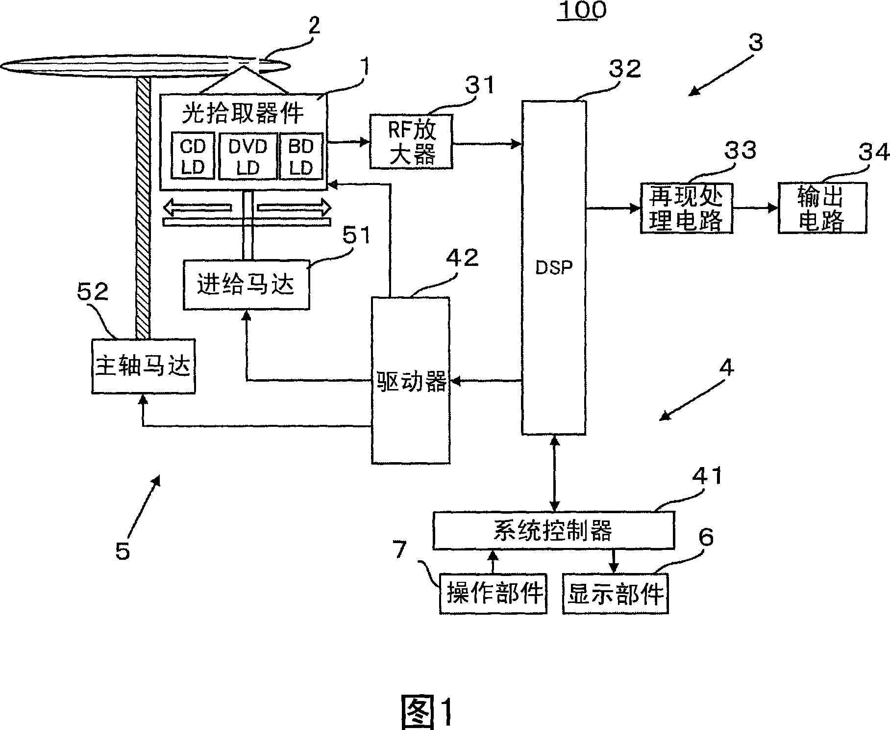
[0035] FIG. 1 is a configuration diagram showing an example of an optical disc player of the present invention. The optical disc player 100 (corresponding to an information reproducing device) has an optical pickup device 1 , an output device 3 , a pointing device 4 , a drive device 5 , a display unit 6 , and an operation unit 7 according to the present invention.

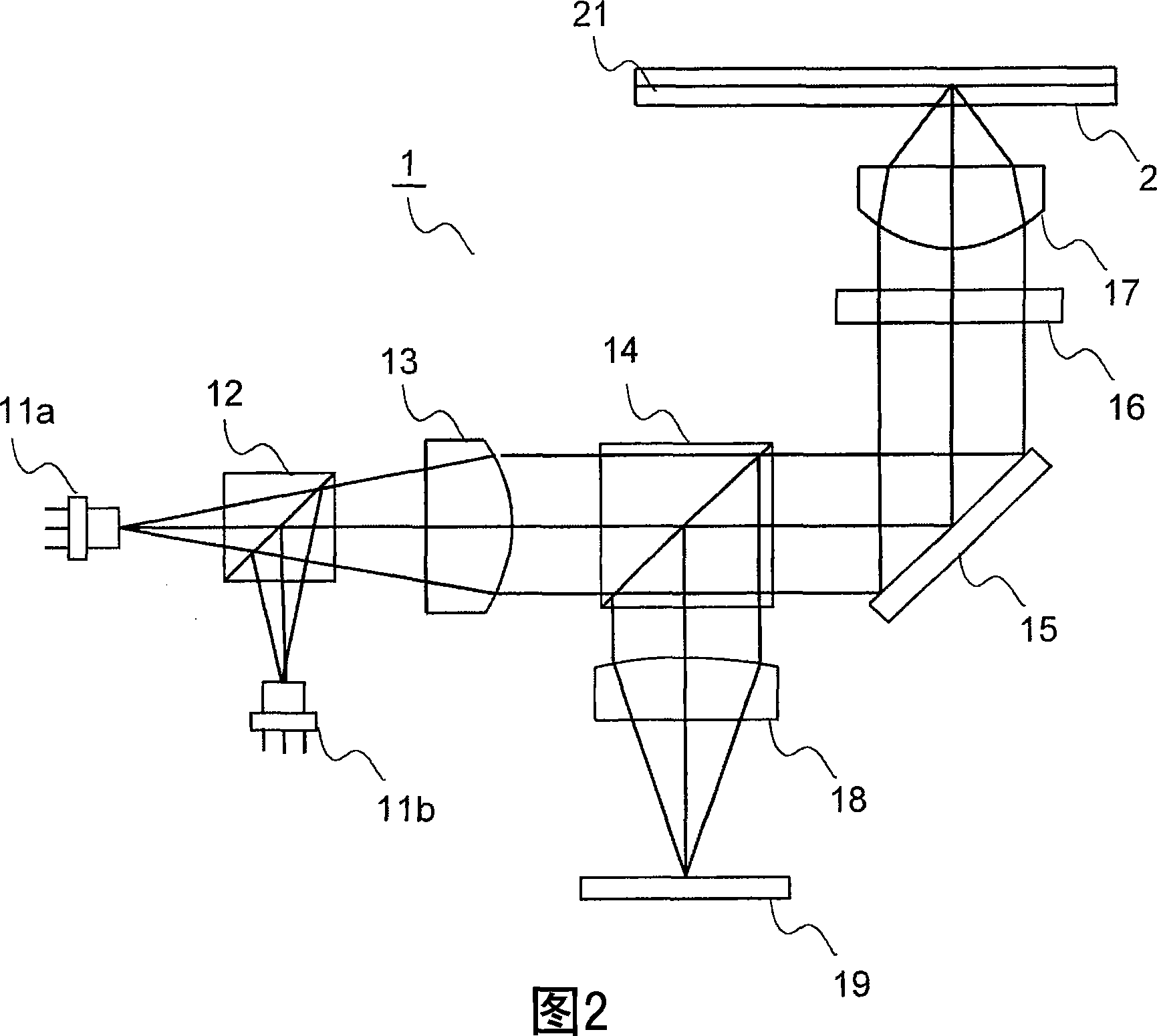
[0036] The optical pickup device 1 reads various information such as audio information and image information recorded on the optical recording medium 2 (CD, DVD, or BD) by irradiating a light beam to the optical recording medium 2 .

[0037] The output device 3 converts information such as sound information and image information from the optical pickup device 1 into sound and images, and outputs them to a speaker and a display not shown in the figure, respectively, and has an RF amplifier 31, a DSP (Digital Signal Processor: digital signal processor) ) 32, reproduction processing circuit 33 and output circuit 34. ...


PUM


Abstract

A drive controller for electrode group A obtains a disc type, a current layer, and a temperature of the liquid crystal element, and based on contents of the information, it obtains drive voltage values to be applied to the electrodes of the group of electrodes A from the set value table. When the drive voltages to be applied to the group of electrodes A are determined, the drive controller for electrode group A finishes the process, and the process flow goes to a process performed by the drive controller for electrode group B. The drive controller for electrode group B performs initialization of segment numbers. Then, it determines how a phase correction quantity of an electrode Am has changed along with an increase of a radius of the liquid crystal element by using graphs and data, so as to determine the drive voltages to be applied to the group of electrodes B by different calculating methods for different areas in which the electrode Am is disposed.

Description

technical field [0001] The present invention relates to an optical pickup device and an aberration correction device included in an information processing device using an optical recording medium, and more particularly to an aberration correction device capable of correcting wavefront aberration, an optical pickup device, an information reproduction device, and an aberration correction device method. Background technique [0002] In recent years, optical recording media such as compact discs (hereinafter referred to as CDs) and digital versatile discs (hereinafter referred to as DVDs) have become widespread and commonly used. In addition, in order to increase the amount of information on the optical recording medium, studies related to the high density of the optical recording medium are being carried out. Modernized optical recording media are also being gradually applied. [0003] When recording and reproducing such an optical recording medium, an optical pick-up device ...

Claims


Application Information

Patent Timeline
Patent Type & Authority Applications(China)
IPC IPC(8): G11B7/125G11B7/135G02F1/13
CPCG11B7/13925G11B7/1369G11B2007/0006
Inventor 紫原哲也清水真弥永座强长岛贤治
Owner FUNAI ELECTRIC CO LTD
Learn More