Slide roller sieve

A technology of sliding roller and sieve bed, which is applied in the direction of sieving, solid separation, grid, etc., which can solve the problems that the screening work cannot be carried out, it is not suitable for the screening of viscous powder and granular materials, and the order of magnitude of the mesh is reduced.

Inactive Publication Date: 2007-10-17
登封电厂集团铝合金有限公司
View PDF0 Cites 16 Cited by
  • Summary
  • Abstract
  • Description
  • Claims
  • Application Information

AI Technical Summary

Problems solved by technology

[0004] However, the vibrating screen has a fatal weakness, that is, it is not suitable for screening viscous powder.
When vibrating sieve is used to screen viscous powder and granular material, sticky powder and granular material particles are easy to stick to the mesh, which reduces the mesh size and fails to reach the predetermined screening target; more seriously, when this When the bonding reaches a certain level, the mesh can be completely blocked, and the screening work cannot be carried out.
Although I have thought of many ways to regularly scrape off the powder and particles bonded on the mesh, the cleaning speed is often not as fast as the bonding speed.

Method used


Image

  • Slide roller sieve
  • Slide roller sieve
  • Slide roller sieve

Examples


Embodiment Construction

[0018] In order to further illustrate the present invention, below in conjunction with embodiment is described in more detail.

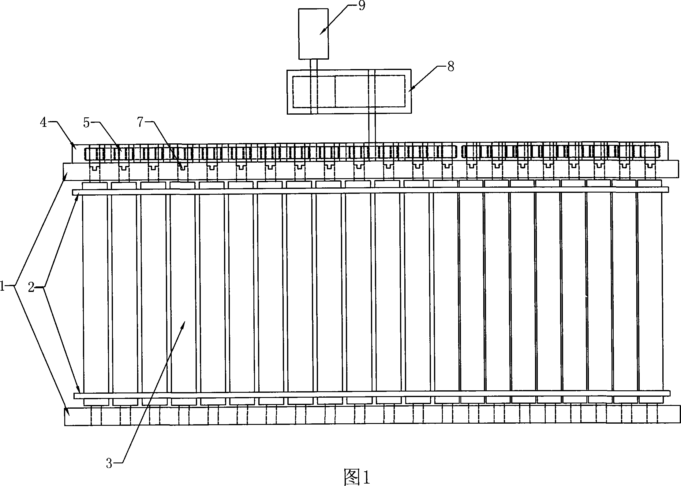
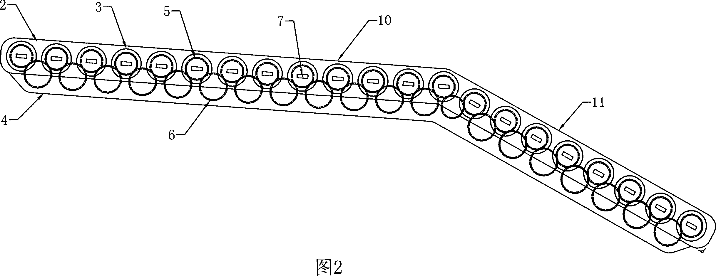
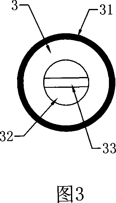
[0019] Figure 1 is a top view of the roller screen, and Figure 2 is a side view of the roller screen. Among them, between two side frames 1 supported by crossbeams, a lot of sliding rollers 3 are placed next to each other, and the side frames 1 are filled to form a sieve bed; these sliding rollers 3 both ends have shaft heads 30, 32 (see Fig. 4), placed in the bearing on the side frame 1.

[0020] Leave a gap between two adjacent slip rollers 3, and this gap is just equivalent to the mesh of screen cloth.

[0021] On one side of the sieve bed, next to the outside of the side frame 1, there is a gear box 4; in the gear box 4, corresponding to each slip roller 3, there is a driving gear 5, the driving gear 5 and the corresponding slip roller 3 The shaft heads 32 are connected by detachable tenons (see Fig. 3 and Fig. 4); that is to say, all the slidi...


PUM

PropertyMeasurementUnit
Diameteraaaaaaaaaa

Abstract

A slippery rolling screen comprises a screening bed that includes two side frames and a plurality of transverse frames, between which a plurality of slippery rollers are arranged one by one. Axle heads of the slippery rollers are equiped into bearings on the side frames, while a clearance is provided between two adjacent slippery rollers; a bear box is arranged outside each side frame and has a drive gear corresponding to the axle heads of each slippery roller, while detachable seam connection is adopt between the drive gear and the axle head; a driven gear is provided on a declined direction of the drive gear and is engaged with two adjacent drive gears; a drive motor is connected with one of drive gears via a reducer; the side frames are in bending shape. While in installing, the screening bed has placing angle of 3-12 DEG on an upper section and that of 28-34 DEG on a lower section. The slippery rolling screen of the invention has self purging function by using the clearance between the two adjacent slippery rollers as a screen, meanwhile the two adjacent slippery rollers moves relatively at a joint position, and can change mesh of the screen by changing slippery rollers in different groups, thus is applicable to screening sticky particle and normal particle.

Description

technical field [0001] The invention relates to an industrial vibration sieve, in particular to a sliding roller sieve suitable for screening viscous powder and granular materials. Background technique [0002] The screening of powder and pellets is an indispensable process commonly used in industrial production. At present, vibrating screens are commonly used as the main equipment. The usual vibrating screen is a screen with a suitable mesh set on a vibrating frame, and is generally placed at a certain downward angle. The powder or pellets to be screened are added to the upper part of the sieve through a feeding device. During the continuous vibration of the vibrating frame, the powder or pellets gradually slide down. , Granules larger than the mesh slide out from the lower end of the vibrating screen for recycling. Through the above-mentioned process, the purpose of powder and granular material screening is achieved. [0003] At present, the vibrating screen is a fairly...

Claims


Application Information

Patent Timeline
IPC IPC(8): B07B1/14B07B1/42B07B1/46
Inventor 刘迎忠高国卿王宏伟屈苏楠王令旗马水涛胡新好付卫欣安志敏尤松昌程跃峰
Owner 登封电厂集团铝合金有限公司
Why Eureka
Try Eureka