Vacuum pneumatic ink containers

An ink and vacuum technology, applied in the direction of packaging under vacuum/special atmosphere, packaging objects under special gas conditions, special packaging objects, etc., can solve the problems of inconvenient production operation and transportation, small outer diameter of sealing cover, incomplete exhaust, etc. problems, to achieve the effect of convenient transportation and filling operations, simple ink extraction operations, and clean and thorough exhaust.

Inactive Publication Date: 2007-10-17
谭慈源
View PDF0 Cites 17 Cited by
  • Summary
  • Abstract
  • Description
  • Claims
  • Application Information

AI Technical Summary

Problems solved by technology

[0002] An earlier disclosed vacuum pneumatic offset printing ink container, Chinese patent 200610000728X discloses a vacuum pneumatic offset printing ink container. The air is discharged from the gap of the air steel sheet. This structure is inconvenient to operate and exhaust, resulting in incomplete exhaust. The residual air makes the ink skin and is not suitable for mechanized operations; the outer diameter of the sealing cover is small, which is inconvenient for production operation and transportation, and is easy to be damaged; use When ink is used, a pneumatic ink outlet device is used to take ink, which is costly, inconvenient to operate, and has a high failure rate

Method used


Image

  • Vacuum pneumatic ink containers
  • Vacuum pneumatic ink containers
  • Vacuum pneumatic ink containers

Examples


Embodiment Construction

[0019] The specific implementation of the vacuum pneumatic ink container will be further described in detail below in conjunction with the accompanying drawings.

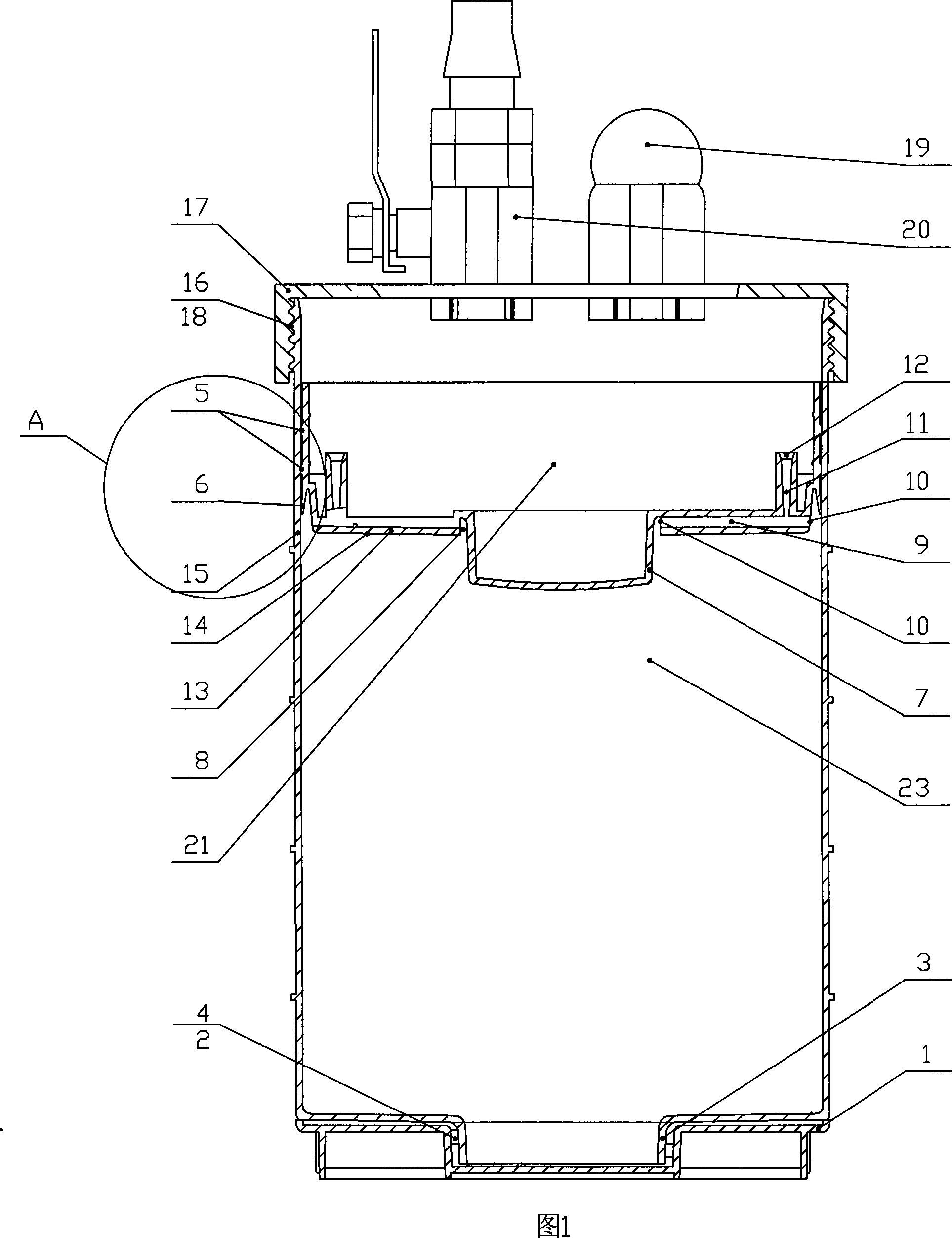
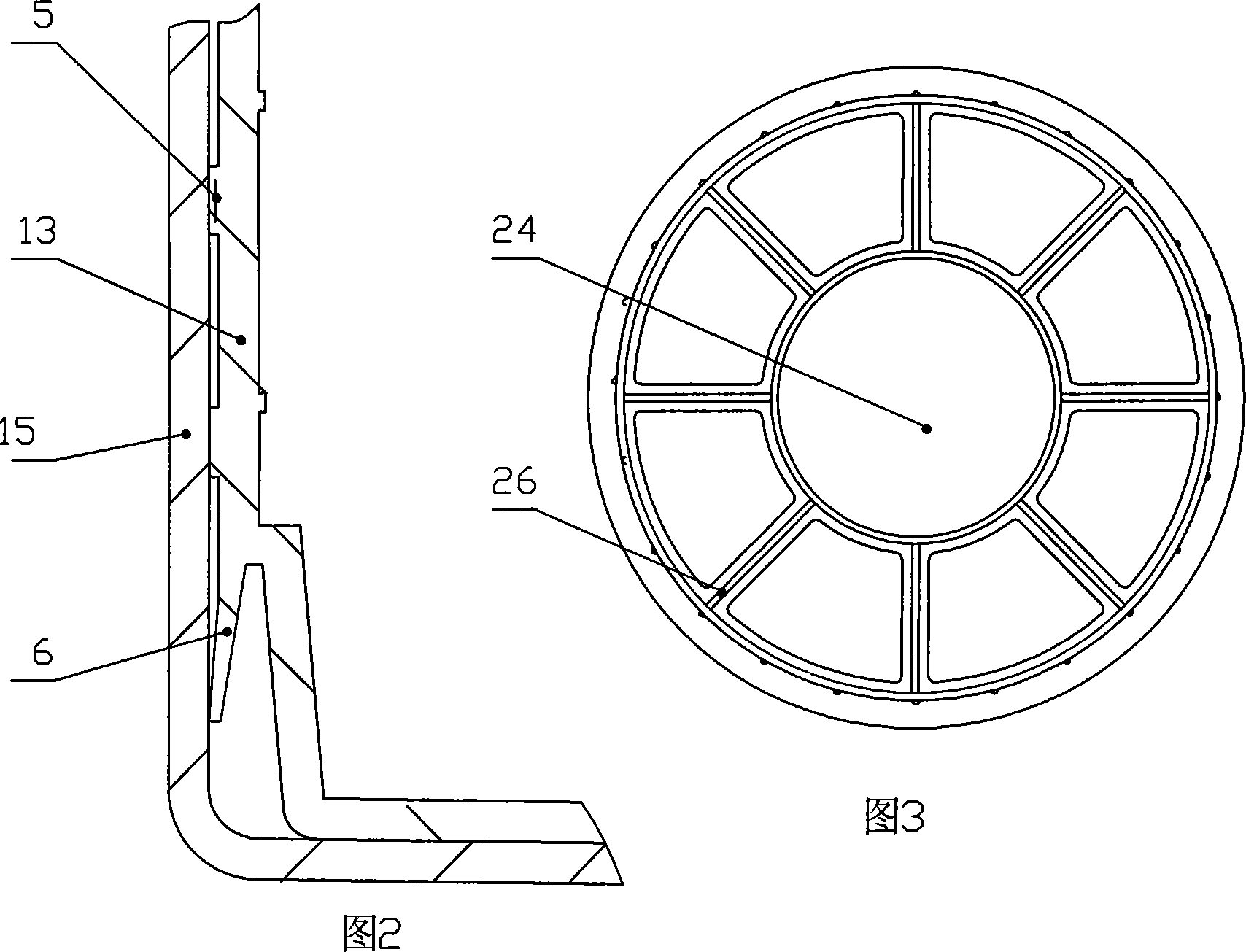
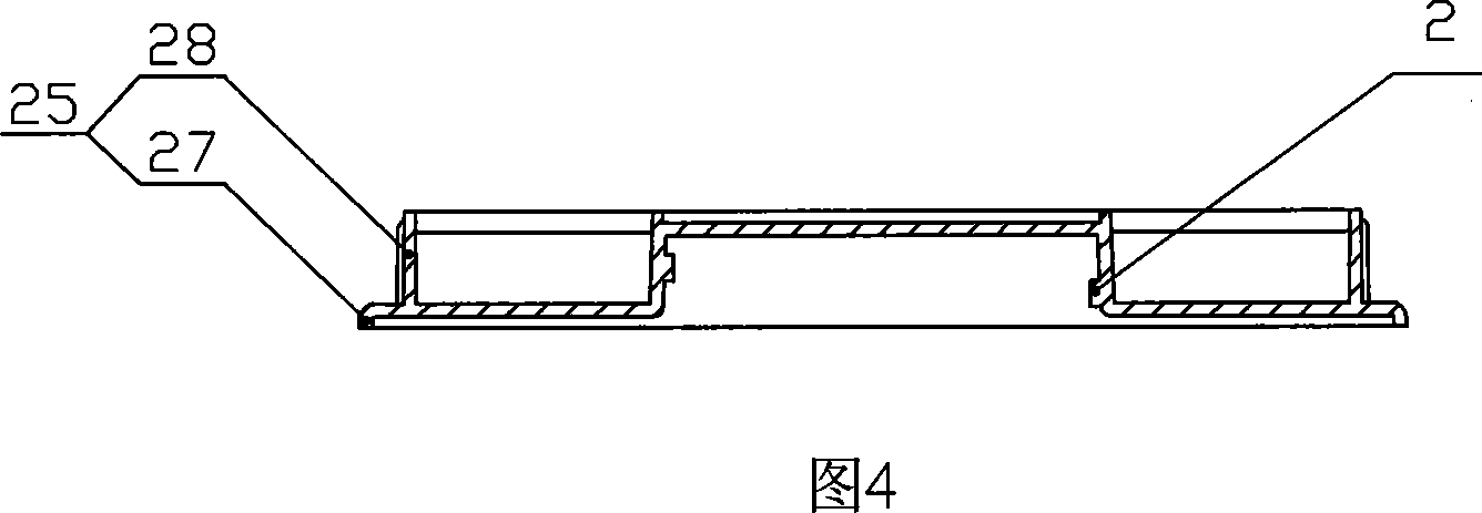
[0020] Referring to Figures 1 to 8, the vacuum pneumatic ink container of the present invention includes a cylinder body 15 and a hollow piston 13 located in the cylinder body 15, the ink is vacuum-packed in the front cavity defined by the cylinder body 15 and the hollow piston 13, and the rear The end is closed by a hollow piston 13. The front end of cylinder body 15 is provided with ink outlet 3, and end cap 1 is housed on it. The front end surface of the hollow piston 13 is provided with a boss 7 matched with the inner hole of the ink outlet 3 . A connecting thread 18 is provided on the side of the outer wall of the rear end of the cylindrical body 15, on which an inflatable sealing cover 17 is housed. When the printing machine needs to add ink, the pressure air enters the cylinder body 15 and the rear cavity (...


PUM


Abstract

The invention relates to a vacuum pneumatic printing ink container which can realize mechanical filling, vacuum packing storage during printing ink production and pneumatic ink taking during printing. The container includes cylinder body and hollow piston, ink outlet, protruding column; air guide inlet holes of the hollow piston are respectively located on inner side face of annulus air guide slot of root portion of the protruding column of the hollow piston and circumference side face of the hollow piston, and two air guide discharge columns are arranged at back end of the hollow piston and are connected to the back cavity in order to completely discharge air; screw thread on ink outlet is tightly screwed with the screw thread of end cover, then the printing ink can be vacuum sealed in front cavity for the convenience of transportation and vacuum storage; outer diameter of the end cover is close to the same of the cylinder, so that force on the printing ink container entirety can be balanced thereby preventing the printing ink container deformation and being damaged; screw thread on peripheral of back end of the cylinder can couple with the screw thread of the aeration seal cover, and gas incoming switch valve on the aeration seal cover is convenient for plugging air tube of air source, and safe pressure limiting valve can relieve the pressure in the back cavity in time, and it is easy to pick and supply the printing ink, and can smoothly output the printing ink, and reduces work intensity.

Description

technical field [0001] The invention relates to an ink container, in particular to a vacuum pneumatic ink container which can be used in the production and use of ink and can adapt to mechanized operations, vacuum packaging and storage, and pneumatic ink extraction during printing. Background technique [0002] The early disclosed vacuum pneumatic offset printing ink container, Chinese patent 200610000728X discloses a vacuum pneumatic offset printing ink container. The air is discharged from the gap of the air steel sheet. This structure is inconvenient to operate and exhaust, resulting in incomplete exhaust. The residual air makes the ink skin and is not suitable for mechanized operations; the outer diameter of the sealing cover is small, which is inconvenient for production operation and transportation, and is easy to be damaged; use When ink is used, a pneumatic ink outlet device is used to take ink, which has high cost, inconvenient operation and high failure rate. Con...

Claims


Application Information

Patent Timeline
Patent Type & Authority Applications(China)
IPC IPC(8): B41F31/02B65D83/76B65D81/20B65D53/00
Inventor 谭慈源
Owner 谭慈源
Why Eureka
Try Eureka