Middle and low speed magnetic levitation track girder

A technology of maglev track and track beam, which is applied to joists, girders, trusses and other directions, can solve the problems of high erection cost, self-heavy weight, and high concrete consumption, so as to reduce concrete consumption, erection cost and project investment. , the effect of reducing volume and self-weight

Inactive Publication Date: 2007-10-17
CHINA RAILWAY DESIGN GRP CO LTD
View PDF0 Cites 25 Cited by
  • Summary
  • Abstract
  • Description
  • Claims
  • Application Information

AI Technical Summary

Problems solved by technology

[0005] However, the existing maglev track beam structure is self-heavy, consumes a lot of concrete, and the erection cost is high. Compared with medium and low-speed maglev trains, the project investment is too large

Method used


Image

  • Middle and low speed magnetic levitation track girder
  • Middle and low speed magnetic levitation track girder
  • Middle and low speed magnetic levitation track girder

Examples


Embodiment Construction

[0031] The present invention will be further described below in conjunction with the accompanying drawings.

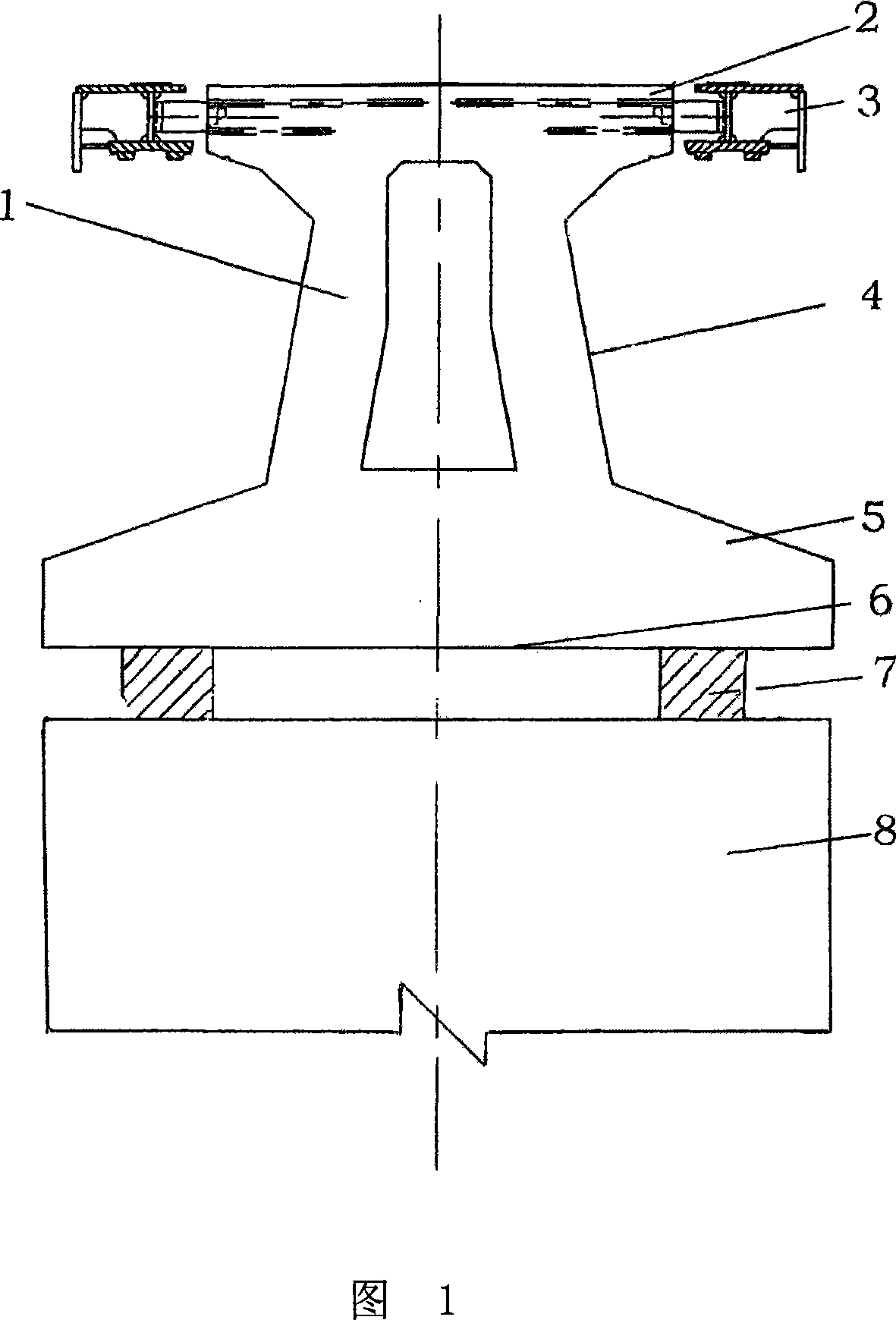
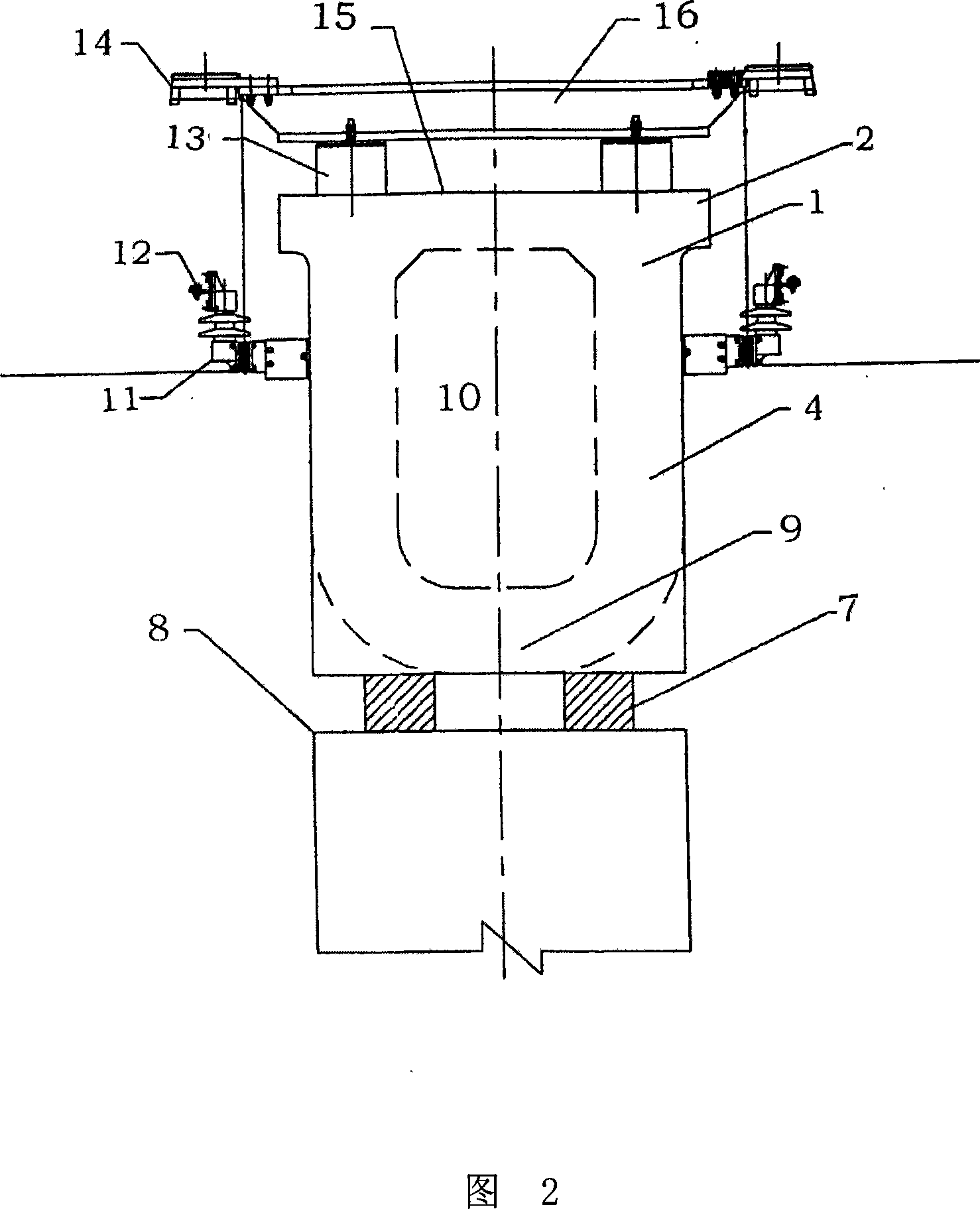
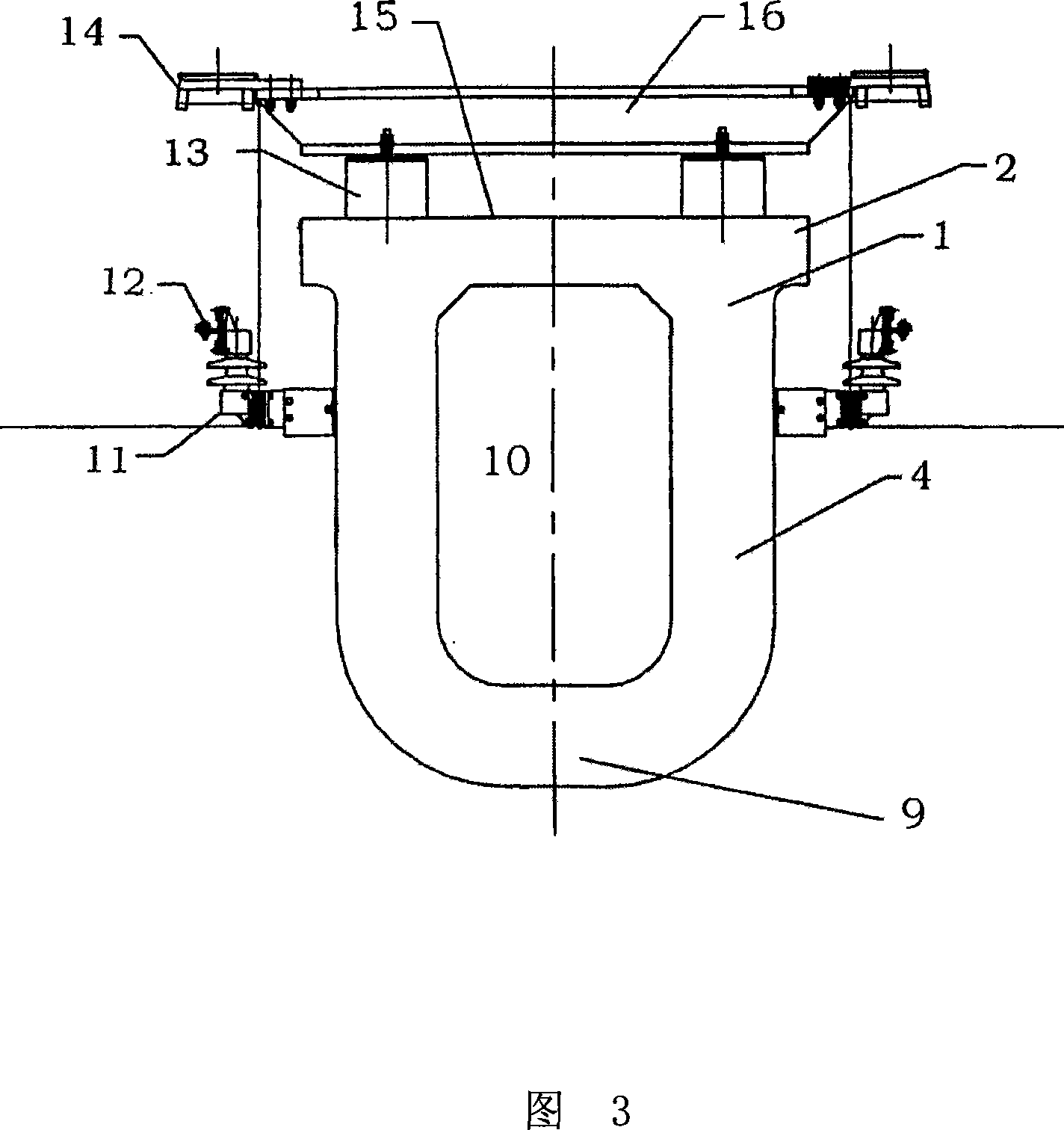
[0032] Fig. 2 and Fig. 3 show the cross-sectional view of the track beam of the U-shaped beam bottom involved in the present invention, Fig. 4 and Fig. 5 respectively show the track beam cross-sectional view of the rectangular and V-shaped beam bottom involved in the present invention, and Fig. 6 shows the present invention The cross-sectional view of the track beam at the fulcrum of the curved section, Figures 7 and 8 show the connection mode of the track beam and the rail row of the present invention.

[0033] As shown in the figure, the medium and low-speed maglev track beam 1 involved in the present invention includes an upper flange 2, a web 4 and a beam bottom 9. The upper flange 2 is located on the top of the track beam 1, and the beam bottom 9 is located at the bottom of the track beam 1. Bottom, the web 4 is placed between the upper flange 2 and the bottom 9 o...


PUM


Abstract

The invention discloses a middle and low speed magnetic float orbit beam, composed of a top flange, a web and a beam bottom, wherein the top flange is disposed on the top of the orbit beam, and the web is arranged between the top flange and the beam bottom. The inner space of the orbit beam span between the pier bearing point is hollow. The outer contour section of the orbit beam is in the rectangle, U-shape or V-shape. At the beam bottom of the pier top is broadened to the rectangle section to install the bearer. The orbit beam retorts along the superelevation arrangement of the line at the curve segment of the orbit line. The web outside of the orbit beam is installed with a diversion orbit frame, and the frame is arranged with a diversion orbit for supply power to the magnetic float vehicles. The beam top side of the orbit beam is provided with a support rail stage, and the support rail stage supports the rail row, while the rail row is fixed on the orbit beam top by the support rail stage. The rail row is arranged with an induction orbit, wherein the induction orbit is vertical to the rail row. The middle and low speed magnetic float orbit beam of the invention can reduce the dead load, lower the consumption of the concrete, reach the effect of reducing the cost and the engineering invest.

Description

technical field [0001] The invention relates to light rail and subway track beams, in particular to the track beams of medium and low-speed maglev trains. Background technique [0002] Maglev train is a comprehensive technology with high technical content in the development of rail transit. The operation of maglev trains, including levitation, guidance, driving and braking, is realized by the electromagnetic force generated by various components arranged on the track beam. Therefore, the structure of the maglev track beam and its erection have high technical requirements, and there needs to be enough space to set up the corresponding components that generate electromagnetic force, and also to be able to withstand various stresses generated by the operation of the train. [0003] The existing maglev track beams are developed based on the requirements of high-speed train operation, and are generally composed of concrete members, including upper flanges, webs, lower flanges, a...

Claims


Application Information

Patent Timeline
Patent Type & Authority Applications(China)
IPC IPC(8): E01D19/00E04C3/20
Inventor 李义兵
Owner CHINA RAILWAY DESIGN GRP CO LTD
Why Eureka
Try Eureka