Same floor draining water backfill layer seeper drainage device

A drainage device and same-layer drainage technology are applied in water supply installations, indoor sanitary pipeline installations, buildings, etc., which can solve the problems of waterproof layer damage, accumulated water leakage, and failure to achieve waterproofing, and achieve low cost, convenient installation, and The effect of simple structure

Inactive Publication Date: 2007-10-17
陆正新
View PDF1 Cites 7 Cited by
  • Summary
  • Abstract
  • Description
  • Claims
  • Application Information

AI Technical Summary

Problems solved by technology

[0003] However, since the invention must first be implemented after the floor slab is settled, it is necessary to make two waterproof layers on the surface of the floor slab and the backfill layer, and the surface waterproof layer is easily damaged during decoration, and the backfilled lightweight concrete has pores, which cannot To achieve the purpose of waterproofing, after the toilet is used for a long time, the water may penetrate downwards into the backfill layer and finally be blocked by the second waterproof layer on the floor surface and stay in the backfill layer. The retained water cannot be discharged and will continue to accumulate. Bacteria and smelly, as the use of time increases, the waterproof layer on the floor may be gradually destroyed, and eventually the accumulated water will leak to the lower floor

Method used


Image

  • Same floor draining water backfill layer seeper drainage device
  • Same floor draining water backfill layer seeper drainage device
  • Same floor draining water backfill layer seeper drainage device

Examples


Embodiment Construction

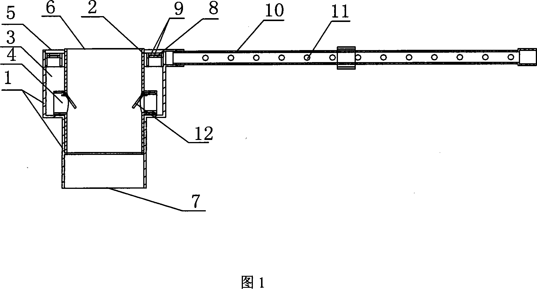
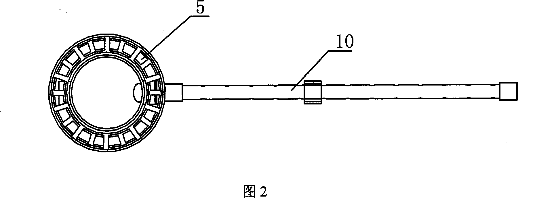
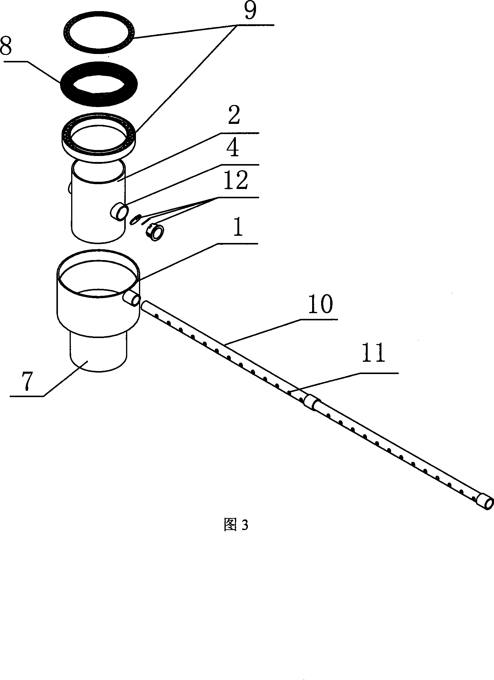
[0014] As shown in Figures 1 to 3, the backfill layer water removal device of the present invention is mainly used in the same-layer drainage system, which includes a shell 1, an inner pipe 2, an upper interface 6, a lower interface 7, and a sand prevention net 8. , Splint 9 and drainage pipe 10; the shell 1 is buried under the bottom surface of the backfill 13 in the floor. The outer diameter of the inner tube 2 is smaller than the inner diameter of the shell 1. When it is installed in the shell 1, a drainage cavity 3 is formed between the two . At the bottom end of the drainage cavity 3, the outer shell 1 is bent inward and is closed and sealed with the inner pipe 2. One or more drainage holes 4 are provided on the wall of the inner pipe 2 near the lower end of the drainage cavity 3. There is also a one-way valve 12 to prevent water backflow; and the upper end of the drainage cavity 3 is open to form a water inlet 5. When installed, the position of the water inlet 5 is flat or s...


PUM


Abstract

The invention discloses a peer drainage backfill layer seeper eliminating device, including a shell and an inner tube, wherein the inner tube is buried in the shell under the backfill layer underside in the floor plate, and a drainage cavity is formed between the shell and the inner tube. At the end lap of the drainage cavity, the inner tube and the shell close to make the end lap of the drainage cavity sealed. A drainage hole is provided on the inner tube wall near the end lap of the drainage cavity, while the top end of the drainage cavity is opened to form an inlet. The upper end of the inner tube has an upper interface for connecting the drainage tie-in or the main pipe, and the lower end of the shell or the tube has an lower interface for connecting the drainage main pipe or the drainage fittings. In order to advance the drainage effect, a drainpipe is laid to communicate with the drainage cavity near the backfill layer underside. The invention adds a simple component on the main drain to solve the seeper problem of the backfill layer in the peer drainage system, which has simple structure, convenient installation, compact connecting conformation between the main sewer and the joint, low cost, without making a water proof layer on the backfill layer.

Description

1. Technical Field [0001] The invention relates to a same-layer drainage system for toilets, in particular to a falling plate type same-layer drainage backfilling layer accumulation water removal device. 2. Background technology [0002] Existing buildings, especially the toilets, are equipped with sewage discharge devices. However, none of the widely used sewage discharge devices can meet the national standards for laying drainage branch pipes in this floor. Holes must be made in the floor during installation. , Install the sewage discharge pipeline of this layer on the top of the toilet on the next floor. The exposed hanging pipe is not only prone to aging and dripping, but also affects the beauty of the toilets of the lower floors. In response to these shortcomings, the applicant filed a Chinese invention patent application named "Same-layer Drainage System" with the application number 200610096701.5. The drainage components and pipelines in this application were first laid on...

Claims


Application Information

Patent Timeline
Patent Type & Authority Applications(China)
IPC IPC(8): E03C1/12
Inventor 陆正新
Owner 陆正新
Why Eureka
Try Eureka