
Composite type oil-hydraulic cylinder

A hydraulic cylinder and composite technology, applied in the direction of cylinders, engine components, mechanical equipment, etc., can solve the problems of not showing the superiority of the combined cylinder, small initial stress, and difficulty in assembling the inner and outer cylinders, and achieve the improvement of initial stress and coordination The effect of reducing the area and overcoming the difficulty of assembly

Inactive Publication Date: 2007-10-17
SHAANXI UNIV OF SCI & TECH
View PDF0 Cites 2 Cited by
  • Summary
  • Abstract
  • Description
  • Claims
  • Application Information

AI Technical Summary

Problems solved by technology

However, there is a practical problem in this combined cylinder, that is, there must be a suitable amount of interference between the inner and outer cylinders. If the interference is large, although the initial stress of the inner and outer cylinders generated by the assembly pressure can be increased, it is difficult to assemble the inner and outer cylinders; If the surplus is small, the initial stress generated is small, so the superiority of the combined cylinder cannot be displayed

Method used


Image

  • Composite type oil-hydraulic cylinder
  • Composite type oil-hydraulic cylinder
  • Composite type oil-hydraulic cylinder

Examples


Embodiment 1

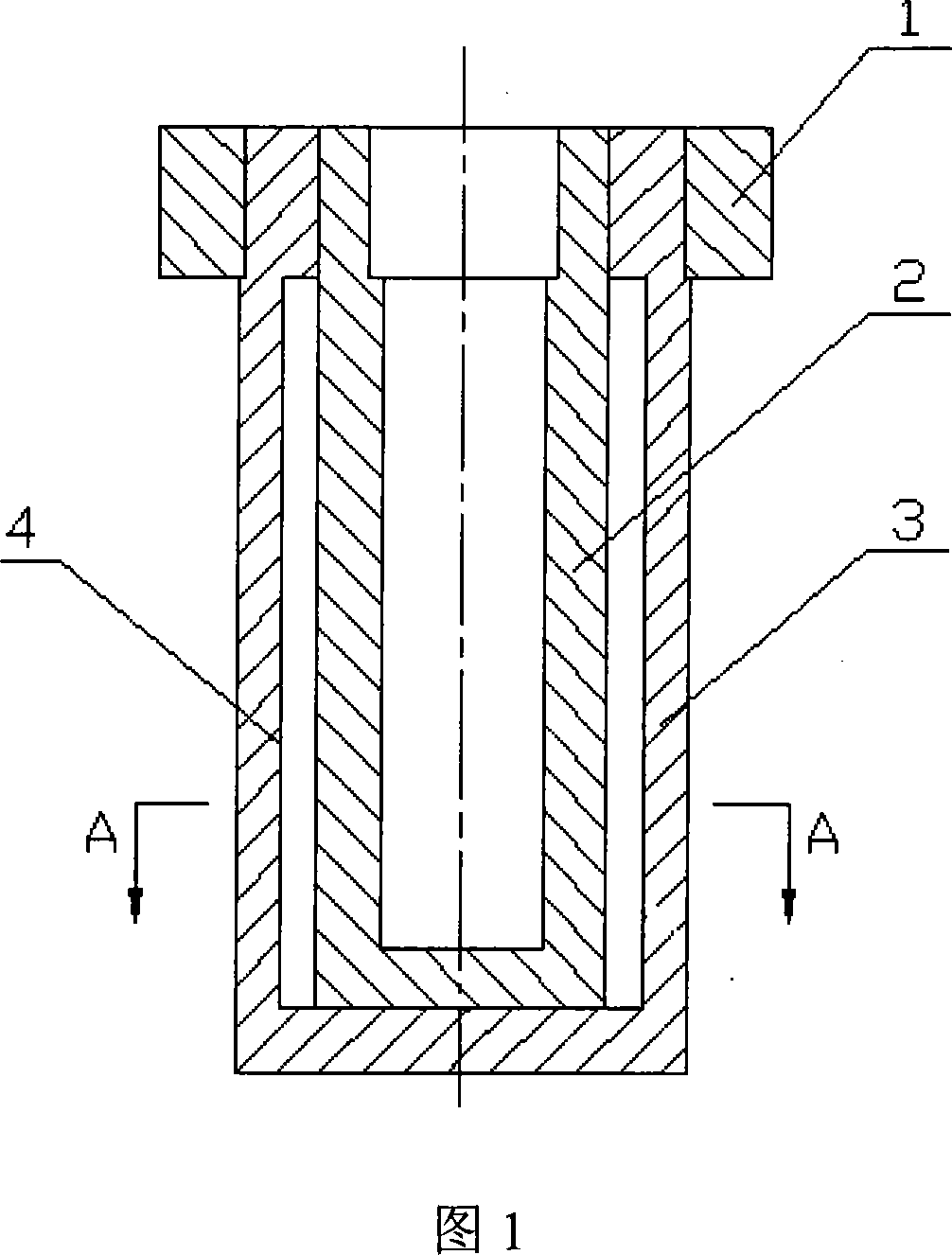
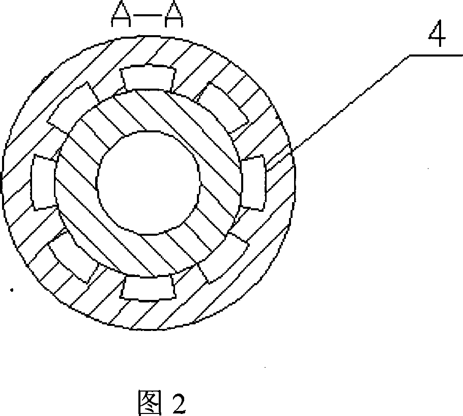
[0015] As shown in Figure 1, a composite hydraulic cylinder of the present invention includes a cylinder end flange 1, an outer cylinder 3, and an inner cylinder 2, and the connection between the cylinder end flange 1 and the outer cylinder 3 is a screw thread Connection, the inner wall of the outer cylinder 3 is connected with the outer wall of the inner cylinder 2, and the connection is an interference fit connection; the inner wall of the outer cylinder 3 is engraved with eight pressure oil grooves 4, which are evenly distributed between the inner and outer cylinders 2 and 3 along the inner wall of the outer cylinder 3 In the meantime, the section of the pressure oil groove 4 is fan-shaped pointing to the center of the cylinder block, which is produced by casting and has reliable strength. The structure of this embodiment can greatly reduce the fit area between the inner and outer cylinders, and the assembly is carried out under a large interference. The initial stress cause...

Embodiment 2

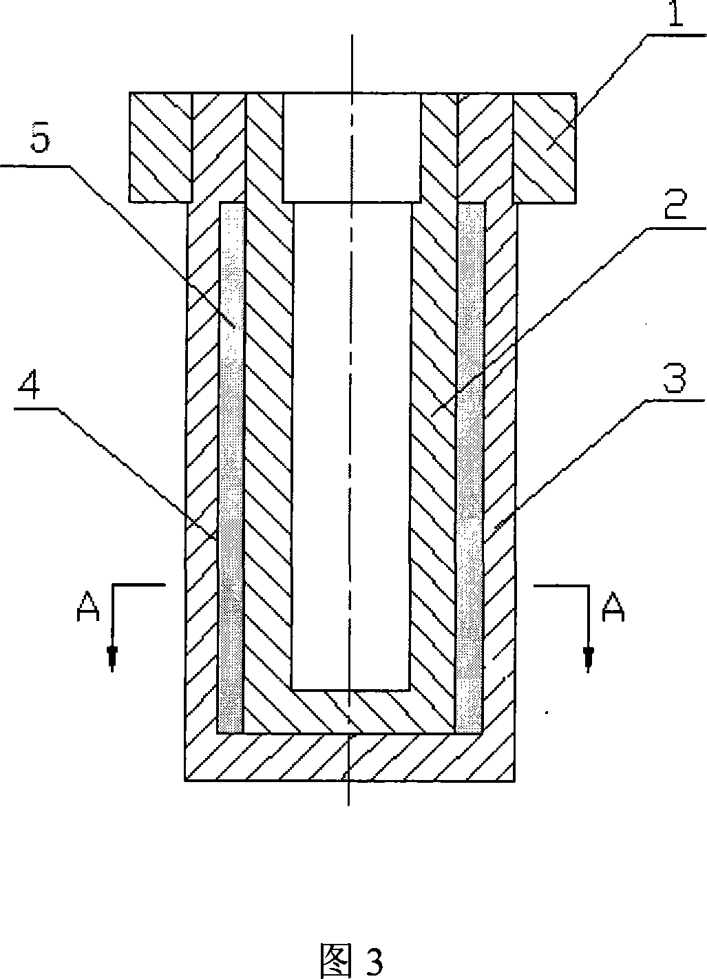
[0017] As shown in Figure 2, another compound hydraulic cylinder of the present invention comprises a cylinder end flange 1, an outer cylinder 3, an inner cylinder 2, and the connection between the cylinder end flange 1 and the outer cylinder 3 is Threaded connection, six oil pressure grooves 4 are engraved on the inner wall of the outer cylinder 3, which are evenly distributed between the inner and outer cylinders 2 and 3 along the circumferential direction of the inner wall of the outer cylinder 3. When the inner and outer cylinders 2 and 3 are assembled, they can be sealed in six pressure oil grooves 4 with a specific gravity of 0.9g / cm 3 30 # Machine oil as high pressure oil5. After filling the high-pressure oil 5 in the pressure oil groove 4, the high-pressure oil can also provide an equivalent initial stress, and the equivalent initial stress and the initial stress provided by the outer cylinder 3 are superimposed and act on the outer wall of the inner cylinder 2. In t...


PUM


Abstract

The present invention improves the fault that the existing combination oil pressure cylinder is difficult in assembly and less in initial stress and provides a high material utilization and strong bearing capability composite type oil pressure cylinder under the condition that the wall thickness of the cylinder is not increased. The cylinder includes an outer cylinder and at least one inner cylinder, the inner wall of the outer cylinder is coupled with the outer wall of the inner cylinder, the coupling is interference fit packing coupling. The inner wall of the outer cylinder is disposed with at least four oil press channels that uniformly disposed between the inner cylinder and the outer cylinder along the circumferential direction of the inner wall of the outer cylinder. The invention has the characteristic of convenient in assembly and distinct reduction in the maximum stress value of the combination cylinder.

Description

technical field [0001] The invention relates to a compound hydraulic cylinder body. Background technique [0002] The oil cylinder is a key part of the press, and it is not an effective and economical way to increase the cylinder wall thickness in order to increase the bearing capacity of the cylinder. Because it is the stress value of a point on the inner wall of the cylinder that determines the strength of the cylinder, when the stress at this point reaches its allowable stress, the cylinder bears the maximum ultimate load. Practice has proved that even if the wall thickness increases a lot, its load-carrying capacity is also slightly improved. At the same time, as the wall thickness of the cylinder increases, the inhomogeneity of the stress in the cylinder wall along the wall thickness is more obvious, so the material of the cylinder cannot be fully utilized. [0003] In order to improve the bearing capacity of the cylinder, the document "Research on the combined cylind...

Claims


Application Information

Patent Timeline
Patent Type & Authority Applications(China)
IPC IPC(8): F16J10/00
Inventor 刘靖耿军岗
Owner SHAANXI UNIV OF SCI & TECH
Learn More