Vibration generation device

A vibration generating device and component technology, which is applied in the direction of fluid using vibration, can solve the problems of large amplitude, slowness, conflict, etc., and achieve the effect of reliable vibration

Active Publication Date: 2007-10-24
ALPS ALPINE CO LTD
View PDF1 Cites 17 Cited by
  • Summary
  • Abstract
  • Description
  • Claims
  • Application Information

AI Technical Summary

Problems solved by technology

[0014] However, in the conventional vibration generating device as described above, if the movable part 54 is intended to generate a low-frequency, large-amplitude, and slow shaking vibration, the upper surface of the movable part 54 may be in contact with the upper surface of the movable part 54. The top plate 51a of the frame body 51 collides, or the coil 55 collides with the bottom 51d of the frame body 51 to generate noise
[0015] As a countermeasure against this, if the distance between the top plate 51a and the bottom plate 51d is increased to prevent the collision of the coils 55, there is a problem that the height dimension of the frame body 51 becomes larger.

Method used


Image

  • Vibration generation device
  • Vibration generation device
  • Vibration generation device

Examples


Embodiment Construction

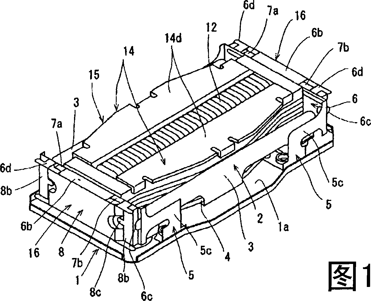
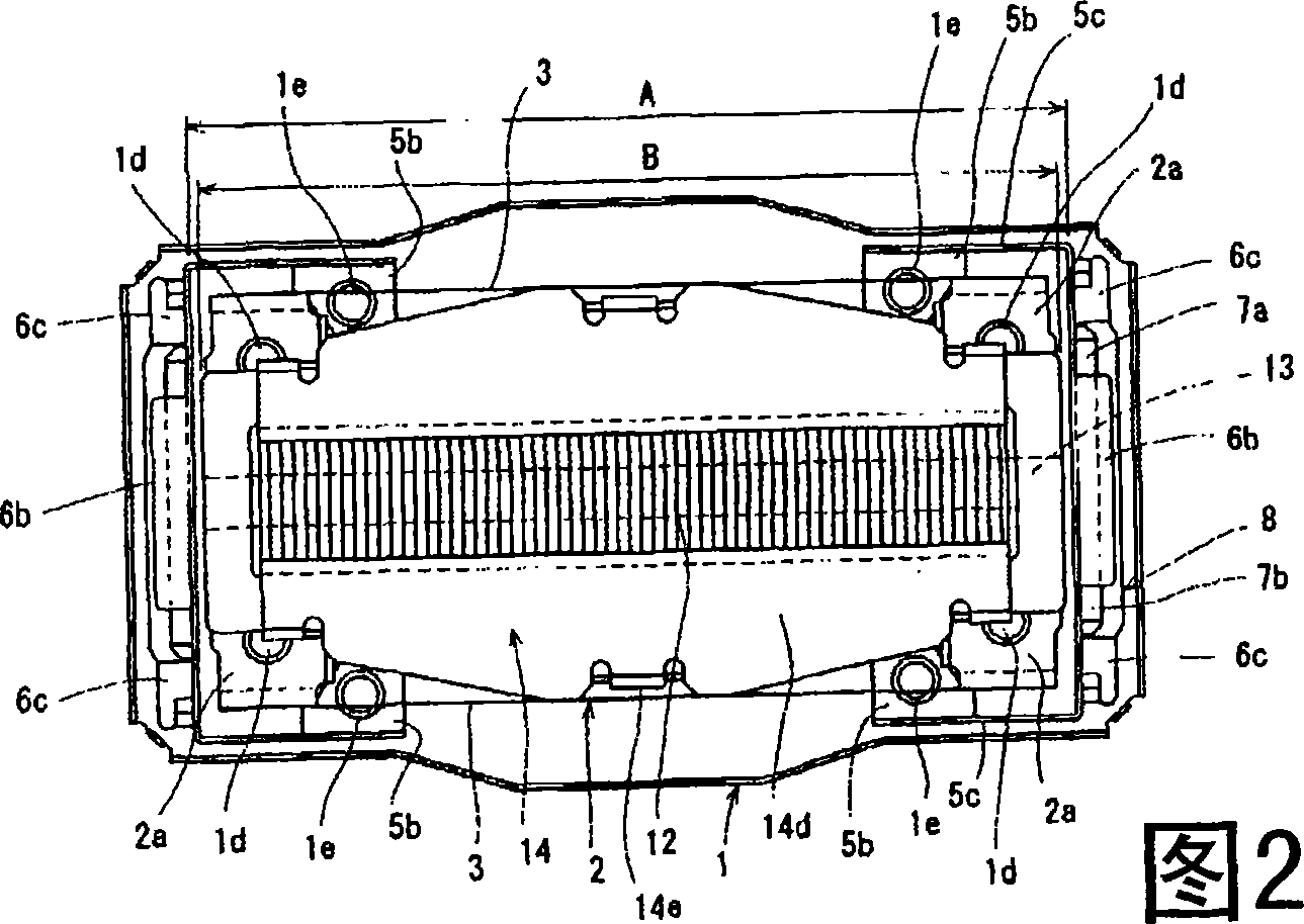
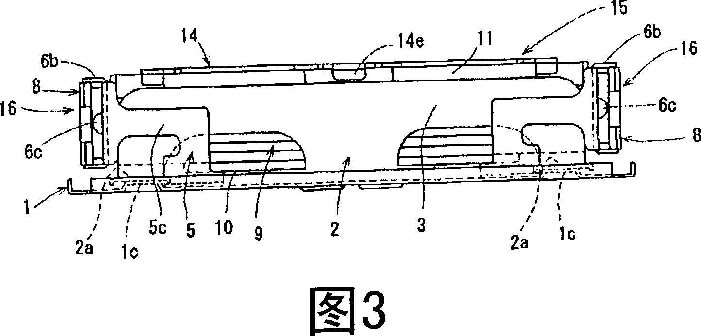
[0060] Next, one embodiment of the vibration generator of the present invention will be described with reference to the drawings. Fig. 1 is a perspective view of a vibration generating device of the present invention, Fig. 2 is a plan view of Fig. 1, Fig. 3 is a front view of Fig. 1, Fig. 4 is an exploded perspective view of Fig. 1, Fig. 5 is an illustration related to a counterweight unit of the present invention An exploded perspective view, Fig. 6 is an exploded perspective view illustrating a magnet unit according to the present invention.

[0061] First, a vibration generating device according to an embodiment of the present invention will be described based on an exploded perspective view of FIG.

[0062] On the bottom plate 1a of the base member 1, a rectangular opening 1b is formed in the center thereof, and at positions close to the left and right ends across the opening 1b, elongated slits are formed at a predetermined height along the arrow Y direction. The protrud...


PUM


Abstract

The present invention provides a device for generating librations which can thin-type ultrasonic and do not generate noise even though oscillating with low frequency and large amplitude. The above mentioned device contains: base part (1) with evenness shape soleplate (1a), the first spring part (2) installed on the mentioned base part (1), and the counterbalance composed of non-magnetic material. The mentioned counterbalance is supported by the first spring part (2) and oscillates in the horizontal direction parallel to the soleplate (1a) of the base part (1). On the above mentioned counterbalance, there are strip-shaped mandrils (13) composed of magnetic material enwind by loop (12), and on the top end of the mandril length direction setting magnet (7) with the regulation interval, inner the above mentioned loop (12) the magnetic flux generated by electrifying acts on the one of the above mentioned magnet (7), thus the above mentioned counterbalance (9) librates in the mentioned horizontal direction through the first spring part (2).

Description

technical field [0001] The present invention relates to a vibration generating device, and more particularly, to a vibration generating device mounted on electronic equipment such as a game machine and capable of improving the sense of presence in a game or the like. Background technique [0002] According to patent document 1, an existing vibration generating device is described. As shown in FIGS. One end portion is a fixed portion 52a, and the fixed portion 52a is fixed on the top plate 51a and supported by a cantilever. [0003] The elastic supporting member 52 is bent obliquely downward in the drawing from the fixed portion 52a to form a deflected portion 52b. The lower part shown in the drawing is bent in the direction parallel to the top plate 51a in the above-mentioned deflection deformation part 52b to form a joint part 53, and the joint part 53 is adhesively fixed to the plate-shaped movable part 54. [0004] Furthermore, a coil 55 and a weight 56 ​​are fixed to t...

Claims


Application Information

Patent Timeline
Patent Type & Authority Applications(China)
IPC IPC(8): B06B1/04
Inventor 铃木克俊
Owner ALPS ALPINE CO LTD
Why Eureka
Try Eureka