Column fully moving grinding machine

A full-moving, column technology, applied in the direction of grinding bed, grinding machine parts, grinding frame, etc., can solve the problem that the single-column grinding machine cannot move in the X direction, and achieve stability and cutting rigidity. Improved balance and anti-vibration performance, improved grinding surface quality

Active Publication Date: 2007-10-24
浙江杭机股份有限公司
View PDF0 Cites 14 Cited by
  • Summary
  • Abstract
  • Description
  • Claims
  • Application Information

AI Technical Summary

Problems solved by technology

[0004] The main purpose of the present invention is to solve the problem that the existing single-column grinding machine cannot move in the X direction, or to change the problem in the prior art that the X direction is only an auxiliary movement for tool displacement, so as to develop a machine tool that uses the X direction movement as a machine tool for grinding. The main cutting movement of the column full mobile grinding machine to improve the applicable performance and degree of automation of the machine tool

Method used


Image

  • Column fully moving grinding machine
  • Column fully moving grinding machine
  • Column fully moving grinding machine

Examples


Embodiment

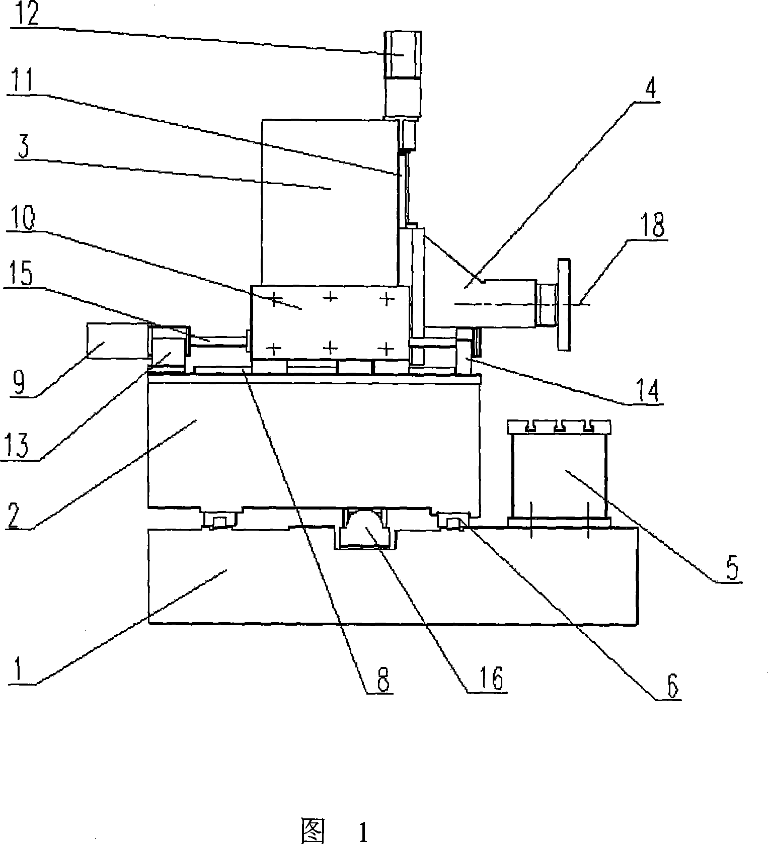
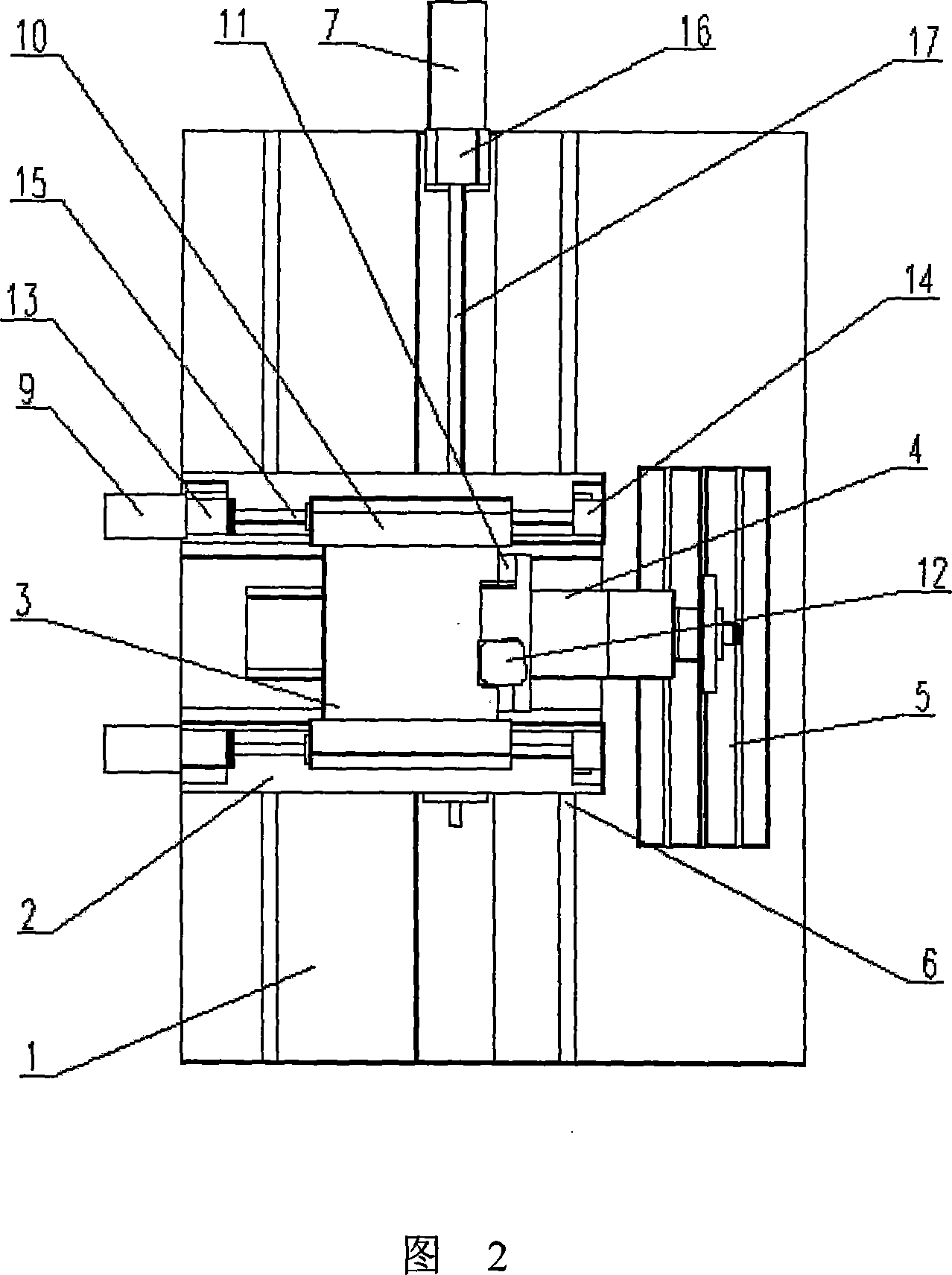
[0019] Embodiment: as shown in Fig. 1 and Fig. 2, the column full-moving grinder, the bed 1 is in the shape of a box-type flat plate, the dimensions of length × width × height: 3200 × 2150 × 427 (mm), and the material is HT250; X-direction movement is installed on it Guide rail 6, two linear rolling guide rails, width × length: 55 × 2880 (mm); X-direction drive mechanism 7 has a ball screw pair 17, specification: ¢50 × 2350 (mm), with casting bracket 16 and X-direction servo The motors are connected in 7 phases, the power / torque of the servo motor 7 is 6.5kW / 41.5Nm, and the maximum feed speed in the X direction is 15000mm / min, which can meet the technical requirements of the main grinding movement. The carriage 2 is U-shaped, the lower part is equipped with a guide rail slider matching the X-direction moving guide rail 6, and the upper part is equipped with a Z-direction moving guide rail 8 and a Z-direction biaxial drive mechanism 9; two linear rolling guide rails, width × len...


PUM


Abstract

The invention relates to a vertical post displacement grinder, comprising the grinder, carriage, grinding head, working platform and side front vertical post, X directional displacement guide track at the bottom of the carriage with the X drive mechanism connected to the machine, both sides of the middle of the vertical post having Z guide track sliders and Z dual axial drive mechanism and connected to the top of the carriage, with the machine in overall case plat, and the working platform fixed on the machine. It improves moving velocity and working efficiency, shortens moving distance, alleviating machine self weight and stability, effectively increasing machining precision, with dual axial gravity drive structure to improve the balance of the horizontal moving force and anti vibration feature for the benefit of the grinding surface quality.

Description

technical field [0001] The invention relates to machine tool processing equipment, in particular to a grinding machine with three-direction full movement of a column and its carriage in X, Y, and Z directions. Background technique [0002] Grinding machine tools in the prior art, such as the layout of surface grinders, most machine tools are designed to adopt a single column fixed type. Although there is a column-moving machine tool, it cannot move in the X direction, but only moves laterally in the Z direction, and the old-fashioned lateral movement mechanism is designed at the bottom of the column, which has a high center of gravity, poor stability, and low precision. At present, there is a new lateral movement device of a mobile column grinding machine. Although the lateral movement device is arranged near the center of gravity of the column, the stability and cutting rigidity of the lateral movement can be increased. However, the lateral drive is only in the form of uni...

Claims


Application Information

Patent Timeline
Patent Type & Authority Applications(China)
IPC IPC(8): B24B41/02B24B41/04B24B47/04B24B47/12B24B47/20
Inventor 骆广进周哲平金凤珠秦炜陈眉谢颖华范炳忠
Owner 浙江杭机股份有限公司
Why Eureka
Try Eureka