Double-path high-pressure heat-exchange device for double-chamber gas quenching furnace

A channel and heat exchanger technology, applied in the direction of quenching device, quenching agent, heat treatment equipment, etc., can solve the problems of speed and difficulty of heat exchange effect, and the space in the furnace cannot be equipped with water-cooled heat exchangers, etc.

Inactive Publication Date: 2007-10-24
WUJIANG TIANDIREN VACUUM FURNACE
View PDF0 Cites 1 Cited by
  • Summary
  • Abstract
  • Description
  • Claims
  • Application Information

AI Technical Summary

Problems solved by technology

But at present, the cooling rate still has a considerable gap for some relatively thick workpieces, and there is still considerable difficulty in the treatment of thick workpieces to achieve the hardness of the outer surface and the core.
The main performance is that more water-cooled heat exchangers cannot be installed in the furnace space. The heat discharge is mainly realized by the heat exchanger, and the flow direction, flow rate and flow velocity of the wind also determine the speed of the heat exchange effect.

Method used


Image

  • Double-path high-pressure heat-exchange device for double-chamber gas quenching furnace
  • Double-path high-pressure heat-exchange device for double-chamber gas quenching furnace

Examples


Embodiment Construction

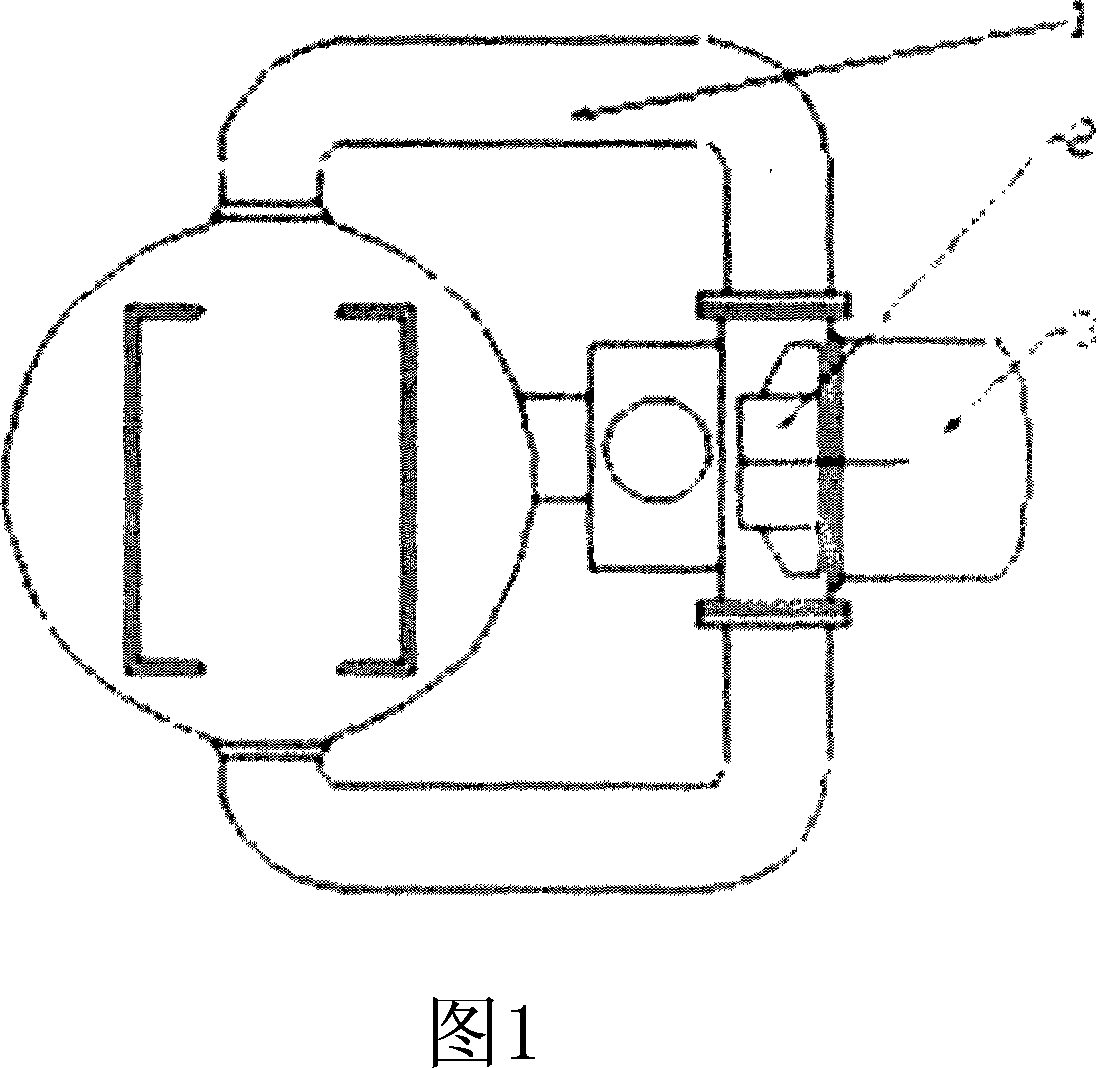
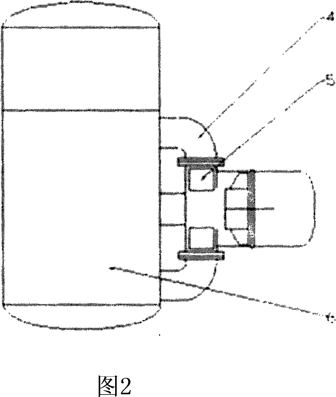
[0010] Below in conjunction with accompanying drawing, the present invention is further described: in cooling chamber (6), connect left and right two air inlets (1) and two outlet pipes (2) up and down, when carrying out cooling operation, blower fan (3) drives impeller ( 2) A cold air flow is blown into the furnace, and after contacting with the hot workpiece, it carries heat and turns into a hot air flow, and the hot air flow enters the heat exchanger (5) to release heat and cool down.

[0011] The equipment is mainly composed of an external circulation fan, a high-pressure fan, and a heat exchanger. The whole heat exchange mechanism is divided into four pipeline inlets and outlets. The heat exchange equipment is equipped with a heat exchanger in front of the front and rear inlets, and the cooling water inlets of the heat exchangers are independent in and out of water, and are connected by pipelines. This greatly increases the cooling rate.


PUM


Abstract

The invention provides a vacuum quenching furnace, which comprises the following parts: power, vacuum chamber, cooling chamber, wherein quenching furnace is equipped with up and down double channel heat exchanger in order to achieve the aim of heat transfer, up and down interface of heat exchanger fire box is admission port, the front and back interface is air drain, the internal of circulating pipe can be equipped with more than two heat exchangers. The invention improves hardenability, which dissolves the difficulty of dealing slab.

Description

technical field [0001] The invention relates to a gas quenching boiler, especially a high-pressure rapid cooling device for a vacuum quenching boiler. Background technique [0002] At present, the advent of high-pressure gas quenching furnace in my country is a great progress in my country's heat treatment industry. Currently He and H above 2MP 2 Gas quenching can basically reach the cooling speed of stationary oil, and the air-cooled surface of the workpiece is smooth and clean, which is both efficient and environmentally friendly. But at present, the cooling rate still has a considerable gap for some relatively thick workpieces, and there is still considerable difficulty in the treatment of thick workpieces to achieve basically the same hardness between the surface and the core. The main performance is that more water-cooled heat exchangers cannot be installed in the furnace space, and the heat discharge is mainly realized by heat exchangers, and the flow direction, flow...

Claims


Application Information

Patent Timeline
Patent Type & Authority Applications(China)
IPC IPC(8): C21D1/62C21D1/613
Inventor 李荣华
Owner WUJIANG TIANDIREN VACUUM FURNACE
Why Eureka
Try Eureka