Heat pipe

A technology for heat pipes and adiabatic sections, applied to heat pipes. In the field, it can solve the problems of high reflux resistance of condensed liquid, hindering the design of forming tools, and increasing the variability of heat transfer performance of heat pipes, etc., and achieve the effects of improving response speed, high capillary pressure, and high porosity

Inactive Publication Date: 2007-10-24
FU ZHUN PRECISION IND SHENZHEN +1
View PDF0 Cites 30 Cited by
  • Summary
  • Abstract
  • Description
  • Claims
  • Application Information

AI Technical Summary

Problems solved by technology

[0005] However, most of the existing heat pipes use a single capillary structure
However, the sintered powder type, wire mesh type, or fiber type are not easy to obtain a consistent capillary structure in the mass production process, and cannot effectively control the porosity and pore size that dominate the heat transfer performance, resulting in increased variability in the heat transfer performance of the heat pipe. And the reduction of efficiency also causes the reflux resistance of the condensed liquid to be large, so that the speed of the condensed liquid is slow and the maximum heat transfer of the heat pipe is reduced; the grooved capillary structure has the same pore size and the flow resistance can be effectively controlled, but its single-layer structure design The porosity of the grooved heat pipe cannot be effectively improved, so its working fluid content will be limited and affect the heat transfer performance of the heat pipe. In addition, the cross-sectional size of the groove on the inner wall of the grooved heat pipe hinders the design of the forming tool, and it is generally difficult to meet the working fluid of the heat pipe. The need for anti-gravity properties
Although some heat pipes currently use a composite capillary structure, most of the composite capillary structures of different forms are in the radial direction of the heat pipe, while the axial direction of the heat pipe is only a composite of different pore sizes and porosities of a single capillary structure.
Therefore, the existing heat pipes do not meet the requirements of different characteristics of the capillary structure corresponding to the different functions of different sections of the heat pipe, which makes it difficult for each section of the heat pipe to perform its functions at the same time, thereby affecting the heat conduction performance of the heat pipe.

Method used


Image

  • Heat pipe
  • Heat pipe
  • Heat pipe

Examples


Embodiment Construction

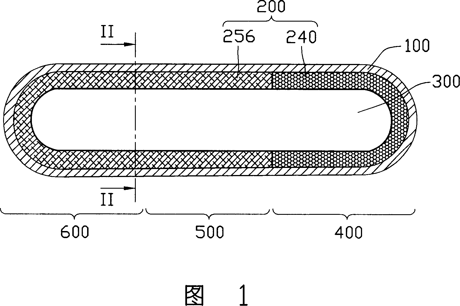
[0015] Please refer to Fig. 1, which is a longitudinal sectional view of the first embodiment of the heat pipe of the present invention; the shown heat pipe includes a metal pipe body 100 with a sealed cavity, and its inner wall is provided with a capillary structure 200, and inside the capillary structure 200 The central space is a steam channel 300, and a proper amount of working fluid (not shown) is sealed inside the metal pipe body 100 and can be moderately pumped to a certain degree of vacuum; The use function can be divided into an evaporation section 400, a condensation section 600 and an adiabatic section 500 between them. Wherein, the metal pipe body 100 is generally made of aluminum, copper or alloys thereof with good thermal conductivity, and its inner wall is smooth or may be provided with several micro-grooves.

[0016] The capillary structure 200 includes a honeycomb first capillary structure 256 and a sintered powder second capillary structure 240 . Please refe...


PUM


Abstract

The present invention discloses a heat pipe, it includes a metal tube which is equipped with a sealed chamber in itself, and the sealed chamber is filled with right amount of work fluid, the inner wall of the metal tube is equipped with capillary structure, the metal tube body is divided into evaporator section, condenser section and insulating section between said both along the length direction, the capillary structure includes the honeycomb first capillary structure installed on the insulating section of the metal tube and the second capillary structure installed on the evaporator section of the metal tube, the first capillary structure is made by metal thin slices, the bore diameter of the second capillary structure is smaller than the bore diameter of the first capillary structure. Said heat pipe is equipped with corresponding capillary structure through the requirements of the sections of heat pipes are corresponding with different capillary structures to use the best functions of the sections of heat pipe effectively.

Description

【Technical field】 [0001] The invention relates to a heat conduction device, in particular to a heat pipe. 【Background technique】 [0002] The heat pipe has the characteristics of ultra-quiet, fast heat transfer, high thermal conductivity, light weight, small size, no moving parts, simple structure and multi-purpose, and the heat pipe can quickly transfer a large amount of heat energy under the condition that the temperature remains almost constant. The role of superconductors is widely used; its basic structure is that the inner wall of the closed tube is lined with a capillary structure layer that is easy to absorb the working fluid, while the central space is in a hollow state, and the equivalent capillary structure is injected into the vacuumed closed tube. The working fluid in the total pore volume of the layer. [0003] The heat pipe can be divided into an evaporating section, a condensing section and an adiabatic section in between according to functions such as absor...

Claims


Application Information

Patent Timeline
Patent Type & Authority Applications(China)
IPC IPC(8): F28D15/04
CPCF28D15/046
Inventor 侯春树刘泰健童兆年柯仙梅孙至贤
Owner FU ZHUN PRECISION IND SHENZHEN
Why Eureka
Try Eureka