Light guide plate, light guide unit arrangement structure and surface light source

A technology of light guide unit and light guide plate, applied in the directions of optical elements, light guides, optics, etc., can solve the problems of affecting visual effects, brightness uniformity limitation, and high density of light guide units 104, avoiding moire and dark lines. Effect

Inactive Publication Date: 2007-10-24
WINTEK CORP
View PDF0 Cites 8 Cited by
  • Summary
  • Abstract
  • Description
  • Claims
  • Application Information

AI Technical Summary

Problems solved by technology

[0006] Furthermore, based on the configuration of the regular arrangement of multiple rings, when the known design divides the light guide plate 100 into a plurality of light guide blocks according to the light radiation direction of the point light source, it will result in two adjacent light guide blocks as shown in FIG. 1 . There is no light guide unit 104 on the boundary between the blocks (ie around the dotted line)
In this way, the light passing through the boundary area will not encounter the micro-scattering element 104 and be difficult to be led out of the light guide plate 100, so that dark lines (corresponding to the position shown by the dotted line in FIG. 1) will be formed on the light guide plate 100, which will affect the visual effect.
[0007] In addition, please refer to FIG. 1 a

Method used


Image

  • Light guide plate, light guide unit arrangement structure and surface light source
  • Light guide plate, light guide unit arrangement structure and surface light source
  • Light guide plate, light guide unit arrangement structure and surface light source

Examples


Embodiment Construction

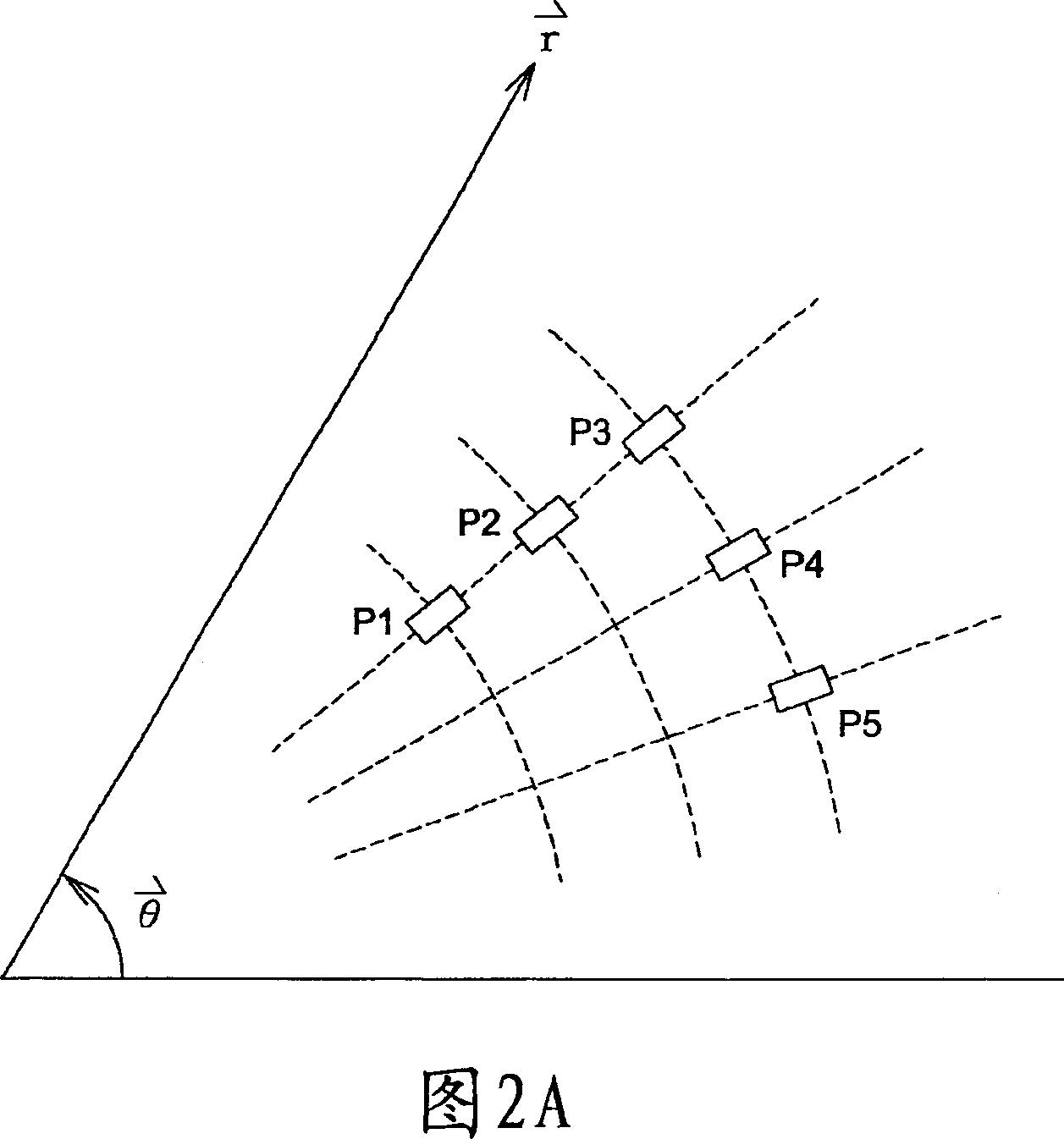
[0036] Before explaining the design of the present invention, the arrangement rules of the light guide units on the plane are clearly defined as follows.

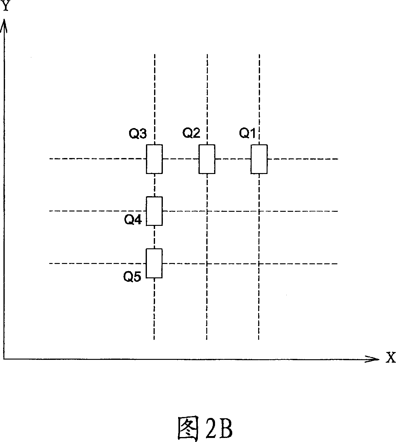
[0037] As shown in FIG. 2A, when the light guide units are distributed on a polar coordinate (polar coordinate) plane, if the light guide units P1, P2, and P3 are substantially arranged in a straight line, it is defined as being arranged along the r direction of the polar coordinates, and as shown in The light guide units P3 , P4 , P5 are arranged on the same concentric circle relative to the origin, and are defined as being arranged along the θ direction of polar coordinates as the angle θ changes. On the other hand, as shown in FIG. 2B, if the light guide units are distributed on a Cartesian coordinate plane, the light guide units Q1, Q2, and Q3 are substantially arranged in a straight line, which is defined as being arranged along the X-axis direction of the Cartesian coordinates. , the light guide units Q3 , Q4 , Q5 are...


PUM


Abstract

The invention discloses a light conductive plate, a light conductive unit arrangement structure and a surface light source device, wherein the light conductive plate comprises a base plate and a plurality of light conductive units on the surface of the base plate, the light conductive units are arranged along two coordinate axis at the surface of the base plate that the light conductive unit row arranged along one coordinate axis is provided with the arrangement offset towards to another coordinate axis.

Description

technical field [0001] The present invention relates to a light guide plate and its arrangement structure of light guide units, in particular to a light guide plate and its arrangement structure of light guide units applicable to point light sources or linear light sources. Background technique [0002] FIG. 1 is a schematic diagram showing a conventional design of a light guide plate with a point light source. The point light source is, for example, a light emitting diode (LED) 102 . As shown in FIG. 1 , since the radiated light wave of the point light source is a spherical wave front, the known design matches the light radiation direction of the point light source, and the light guide unit 104 on the substrate 106 is arranged in a ring along the r and θ directions of the polar coordinates. The rings are regularly arranged concentric circles, so that the light guide plate 100 can obtain better light guide efficiency (light output efficiency), and each light guide unit 104 ...

Claims


Application Information

Patent Timeline
IPC IPC(8): G02B6/00G02F1/13357G02F1/1335
Inventor 陈冰彦方崇仰
Owner WINTEK CORP
Why Eureka
Try Eureka