Dual-frequency and dual-circular-polarization antenna

A polarized antenna, dual circular technology, applied to antenna unit combinations, antennas, antenna arrays and other directions with different polarization directions, can solve the problem of inability to transmit and receive circularly polarized signals

Inactive Publication Date: 2007-10-24
TATUNG COMPANY +1
View PDF0 Cites 3 Cited by
  • Summary
  • Abstract
  • Description
  • Claims
  • Application Information

AI Technical Summary

Problems solved by technology

Therefore, known dual-band linearly polarized antennas cannot transmit and receive any circularly polarized signals

Method used


Image

  • Dual-frequency and dual-circular-polarization antenna
  • Dual-frequency and dual-circular-polarization antenna
  • Dual-frequency and dual-circular-polarization antenna

Examples


Embodiment Construction

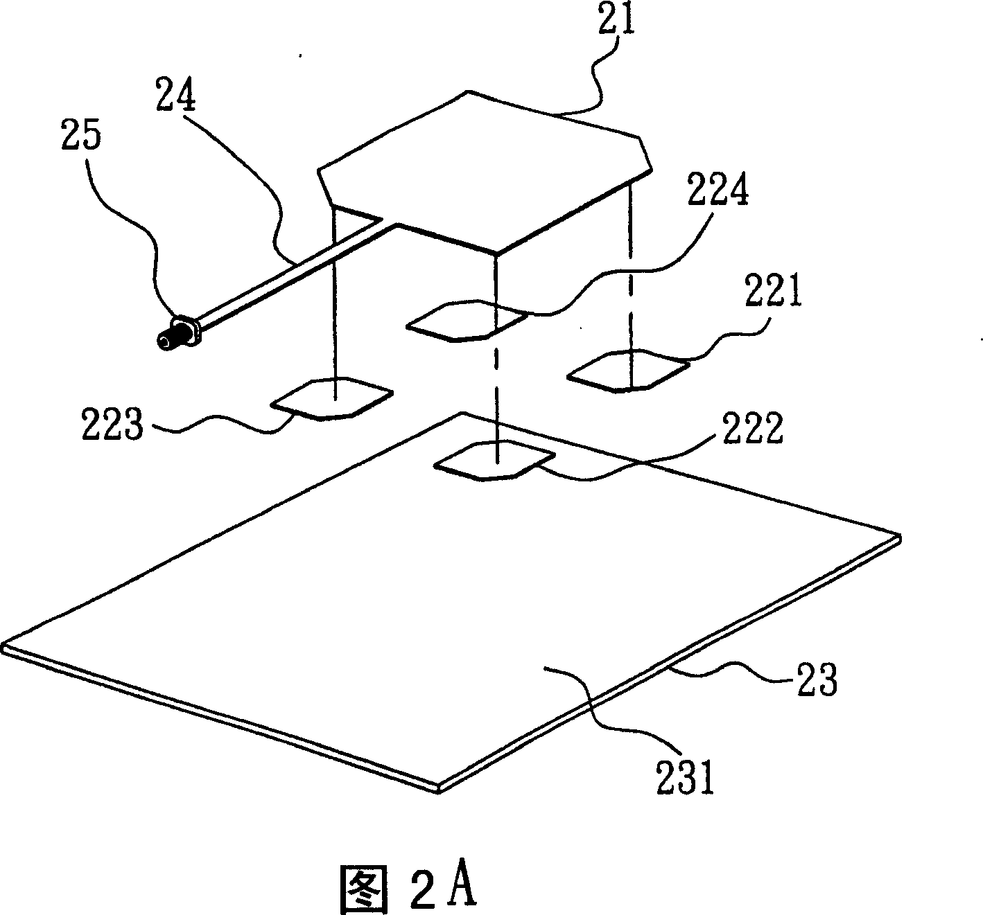
[0023]FIG. 2A is a three-dimensional schematic diagram of a dual-frequency dual circularly polarized antenna of the first preferred embodiment of the present invention, which is integrated in a radio frequency identification (RFID system) antenna module, so that the antenna module can simultaneously operate in the UHF frequency band (between 860 and 930MHz) and microwave frequency bands (between 2.45 and 2.55GHz) to transmit and receive circular polarized signals (circular polarized signal). Therefore, as shown in FIG. 2A, the dual-frequency dual circularly polarized antenna of the first preferred embodiment of the present invention includes a first polarized antenna unit 21, four second polarized antenna units 221, 222, 223, 224 and ground plate 23 . Wherein, in order to simplify the figure, the first microwave substrate carrying the first polarized antenna unit 21 and the second microwave substrate carrying the second polarized antenna units 221 , 222 , 223 , 224 are omitted...


PUM


Abstract

The disclosed dual-frequency dual-circular polarized antenna comprises: a first polarized antenna unit with at least one edge as chamfering, composite second polarized antenna units every with at least one edge as chamfering, an electric signal distributor, a signal-matching unit connecting with the first antenna unit and distributor, and a grounding plate. This invention reduces cost, simplifies system structure, and can be used in RF-ID system conveniently.

Description

technical field [0001] The invention relates to a dual-frequency dual circular polarization antenna, in particular to a dual-frequency dual circular polarization antenna capable of simultaneously transmitting and receiving circular polarization signals in two different frequency bands. Background technique [0002] In some applications, such as radio frequency identification system (RFID), base station of mobile communication system or satellite communication system, the antenna module used must be able to transmit signals with circular polarization characteristics in two different frequency bands at the same time and receive it. However, the currently used circularly polarized antenna can only transmit and receive circularly polarized signals in a single frequency band, and it still cannot transmit and receive circularly polarized signals in two different frequency bands at the same time. On the other hand, although there are currently dual-frequency antennas that can simu...

Claims


Application Information

Patent Timeline
Patent Type & Authority Applications(China)
IPC IPC(8): H01Q21/00H01Q21/24H01Q13/08
Inventor 张知难
Owner TATUNG COMPANY
Why Eureka
Try Eureka