Permanently excited synchronous machine comprising suppression means for improving torque irregularities

A synchronous motor and permanent magnet technology, applied in synchronous motors with stationary armatures and rotating magnets, electric components, electromechanical devices, etc., can solve the problems of torque fluctuation, reduce torque fluctuation, etc., to suppress torque fluctuation stability, low stray field, easy alignment effect

Active Publication Date: 2007-10-24
SIEMENS AG
View PDF2 Cites 9 Cited by
  • Summary
  • Abstract
  • Description
  • Claims
  • Application Information

AI Technical Summary

Problems solved by technology

Furthermore, it is known from DE 19961760 A1 that both the special winding coefficient of the winding system housed in the slot and the inclination of the slot lead to reduced torque fluctuations
Despite these known measures, there are always torque fluctuations, especially in the case of simultaneous manufacture of synchronous motors with permanent magnet excitation at the lowest possible cost

Method used


Image

  • Permanently excited synchronous machine comprising suppression means for improving torque irregularities
  • Permanently excited synchronous machine comprising suppression means for improving torque irregularities
  • Permanently excited synchronous machine comprising suppression means for improving torque irregularities

Examples


Embodiment Construction

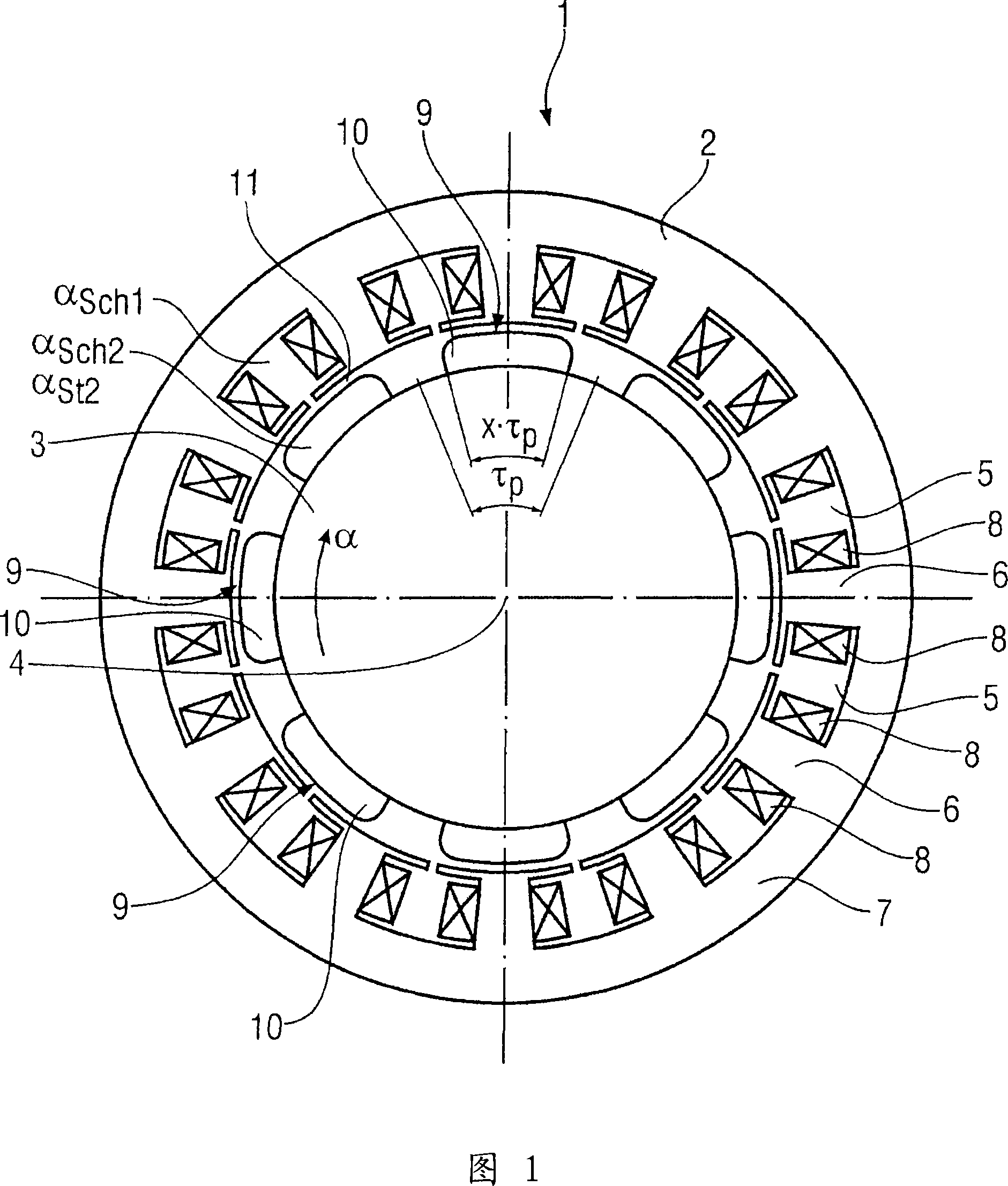
[0028] FIG. 1 shows a permanent-magnet-excited synchronous motor designed as a motor in cross-section. It contains a stator 2 and a rotor 3 mounted rotatably about an axis of rotation 4 . The rotor 3 is an inner rotor. On its inner wall facing the rotor 3 , the stator 2 comprises a plurality of, in the exemplary embodiment of FIG. 1 , a total of twelve slots 5 uniformly distributed around the circumference, between which teeth 6 are formed. The outer ring yoke 7 connects the teeth 6 to one another. The tooth winding coils 8 each surrounding a tooth 6 are arranged in the slot 5 . The rotor 3 is provided with permanent magnets 9 which are arranged so that a total of eight magnetic poles 10 are evenly spaced around the circumference. Here, each magnetic pole 10 corresponds to a pole pitch τ formed by the angular range of the circumferential angle α P . The permanent magnet 9 is not along the pole pitch τ in the circumferential direction P extends over the entire angular ran...


PUM


Abstract

A convertible rotary seal has a housing for receiving a polish rod. A mandrel is rotatably mounted in the seal housing and surrounds the polish rod. A wear sleeve surrounding the mandrel engages a primary seal. A secondary seal engages the mandrel and polish rod and rotates therewith but may be converted for use as a static seal if necessary. A locking mechanism selectively secures the mandrel in a stationary orientation with respect to the seal housing. Fluid that leaks past the primary seal will be detectible through an external orifice. If a leak in the primary seal is detected via the external port, then the mandrel may be secured in a stationary orientation with respect to the housing and the secondary seal may be reconfigured to operate as a stationary seal until such time as the rotary sealing unit can be overhauled.

Description

technical field [0001] The invention relates to a permanent magnet excited synchronous motor comprising a stator provided with slots and a rotor provided with permanent magnets forming magnetic poles. Background technique [0002] Such permanently magnet-excited synchronous motors often have a certain torque fluctuation during operation. Various suppression devices are known to reduce such torque fluctuations. It is described, for example, in DE 10041329 A1 that a rotor surface with permanent magnets having a pole arc factor of 70 to 80% leads to improved harmonic field behavior. Furthermore, it is known from DE 19961760 A1 that both the specific winding factor of the winding system installed in the slot and the inclination of the slot lead to a reduction of the torque fluctuation. Despite these known measures, there are always torque fluctuations, which occur in particular in the case of synchronous motors with permanent magnet excitation which are simultaneously required...

Claims


Application Information

Patent Timeline
Patent Type & Authority Applications(China)
IPC IPC(8): H02K1/27H02K21/12
CPCH02K21/12H02K1/278H02K29/03
Inventor 马赛厄斯·布朗霍尔格·申克罗尔夫·沃尔默
Owner SIEMENS AG
Why Eureka
Try Eureka