Hydraulic press for plastic and metal processing

A technology for metal processing and hydraulic presses, applied in the field of hydraulic presses, can solve problems such as high power peaks, and achieve the effects of small circulating hydraulic oil volume, energy saving, and cooling power reduction

Active Publication Date: 2007-10-31
DIEFFENBACHER GMBH & CO KG
View PDF10 Cites 7 Cited by
  • Summary
  • Abstract
  • Description
  • Claims
  • Application Information

AI Technical Summary

Problems solved by technology

[0013] e) High power peaks occur in the electric-driven free-running bridge, which has disadvantages for operating economy and for increased control technology requirements at the power supplier

Method used


Image

  • Hydraulic press for plastic and metal processing
  • Hydraulic press for plastic and metal processing
  • Hydraulic press for plastic and metal processing

Examples


Embodiment Construction

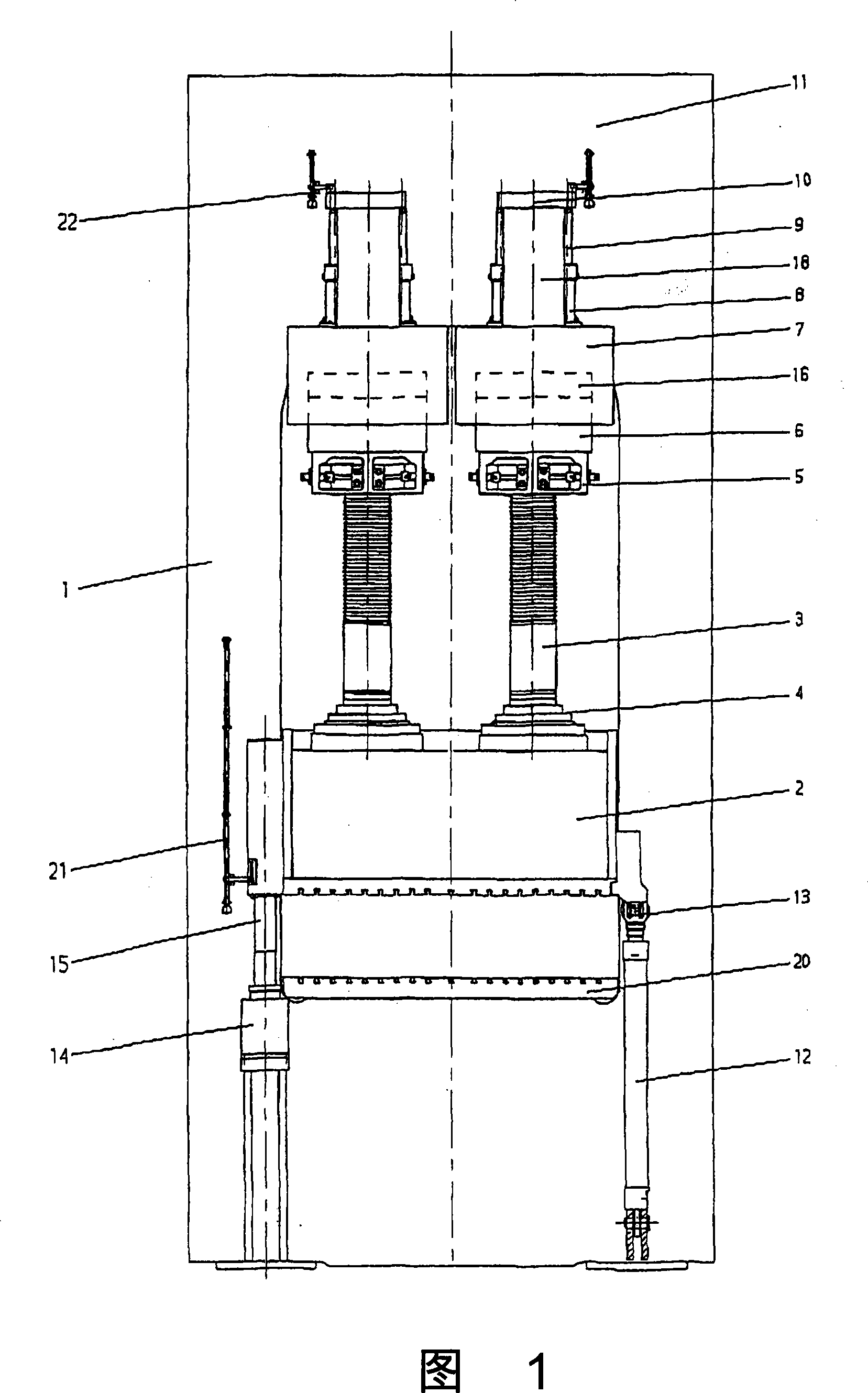
[0025] 1 shows a schematic sectional view of a hydraulic press in the opened state, with a press frame 1 , a press table 20 fixedly arranged thereon, and a press punch 2 arranged displaceably above it. To move the press punch 2 in the rapid stroke, a rapid stroke cylinder 12 is arranged laterally on the punch adapter 13 . A toothed rack 3 is articulated via a hydraulic bearing 4 above the press punch 2 according to implementation requirements and necessity, and the toothed rack is guided in the center bore of the piston 6 of the working cylinder 7 . In this case, the piston 6 has an extension 18 for reliable guidance of the toothed rack 3 and at the same time protects the toothed rack 3 from environmental influences.

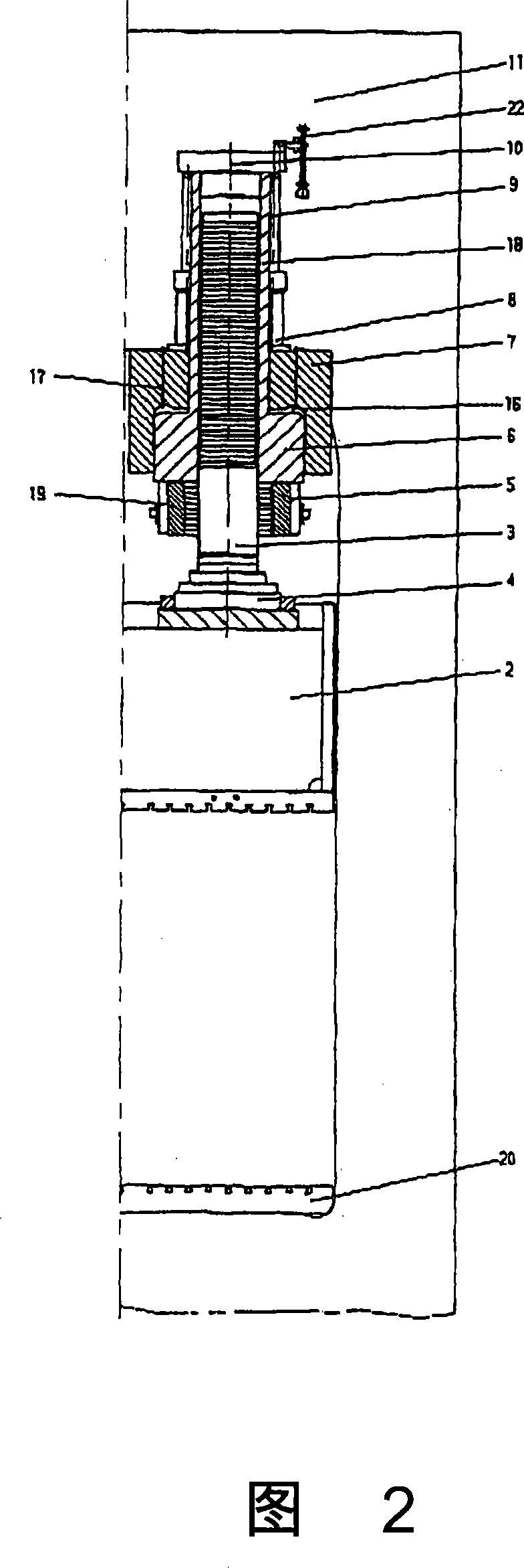
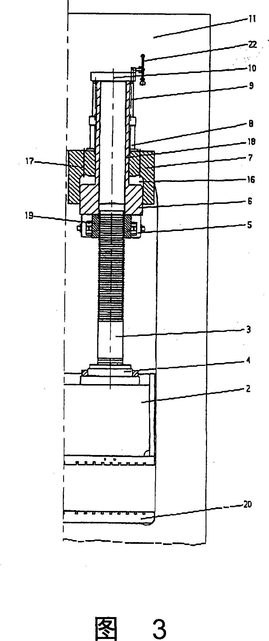
[0026] An enlarged view of the press in the open state can again be seen in FIG. 2 . At this time, the clutch pawl 5 is opened, and the piston 6 of the main hydraulic cylinder 7 is located at the top dead center. The above-mentioned situation can be achieved w...


PUM


Abstract

The invention relates to a hydraulic press for plastic and metal processing, wherein the invention is to provide a hydraulic press which can reduce the period and adjust the crossover of no-load stroke quickly and variably. The hydraulic press can include a press frame (1) with a press table (20) arranged thereto and a traveling press platen (2) arranged therein, in which at least one rapid motion cylinder (12) with a platen connection (13) can be arranged for the rapid no-load stroke of the press platen (2), in which a working cylinder (7) with a piston (6) directed toward the press table (20) can be rigidly arranged on the upper crosshead (11) of the press frame (1), in which a coupling device (5) and opposed thereto a crosshead (10) with a positioning and synchronizing cylinder (9) forthe piston (6) can be arranged on the piston (6) toward the press table (20), in which the piston (6) can include a centrically arranged cylindrical extension (18) for the sliding guide of a connecting device, such as a toothed rack (3), in which this connecting device can be connected to the press platen (2).

Description

technical field [0001] The invention relates to a hydraulic press for plastics and metal processing according to the subject matter of claim 1 . Background technique [0002] A fast-moving hydraulically driven press for plastics and metal processing is known, in which the stroke of the working cylinder can be dimensioned for different tool heights and opening lifts, that is, according to the desired The tools used can likewise utilize the maximum expected tool height in the insertion space between the press table top and the press punches (larger gap between the fastening base of the press table and the press punches) and the required lift as well as the low tool height (small gap between the fastening base of the press table and the press punch). Because this type of press requires an oil column up to 2.5m, the corresponding working surface and the high processing pressure ratio in the tool, there is a large oil volume in the working cylinder, which in addition to causing ...

Claims


Application Information

Patent Timeline
Patent Type & Authority Applications(China)
IPC IPC(8): B30B1/32B30B15/16
CPCB30B15/161B30B1/323B30B15/0035B30B1/34
Inventor R·布鲁塞尔A·赛茨
Owner DIEFFENBACHER GMBH & CO KG
Why Eureka
Try Eureka