Construction steel structure glue-joint technique

A technology of structural glue and construction steel, which is applied in the direction of building construction, construction, measuring devices, etc., to achieve the effect of improving production efficiency, reducing production cost, and good shear resistance

Inactive Publication Date: 2007-10-31
HANGZHOU HENGDA STEEL STRUCTURE
View PDF0 Cites 14 Cited by
  • Summary
  • Abstract
  • Description
  • Claims
  • Application Information

AI Technical Summary

Problems solved by technology

However, there is no report on the bonding of steel structural members.

Method used


Image

  • Construction steel structure glue-joint technique
  • Construction steel structure glue-joint technique
  • Construction steel structure glue-joint technique

Examples


example 1

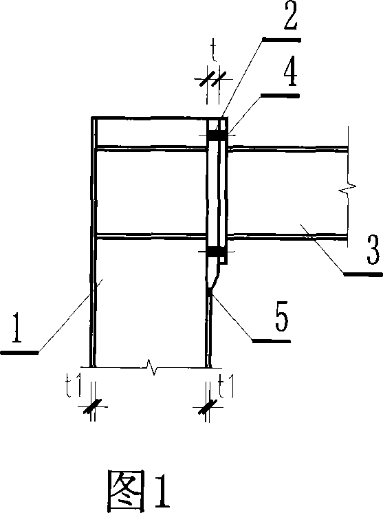
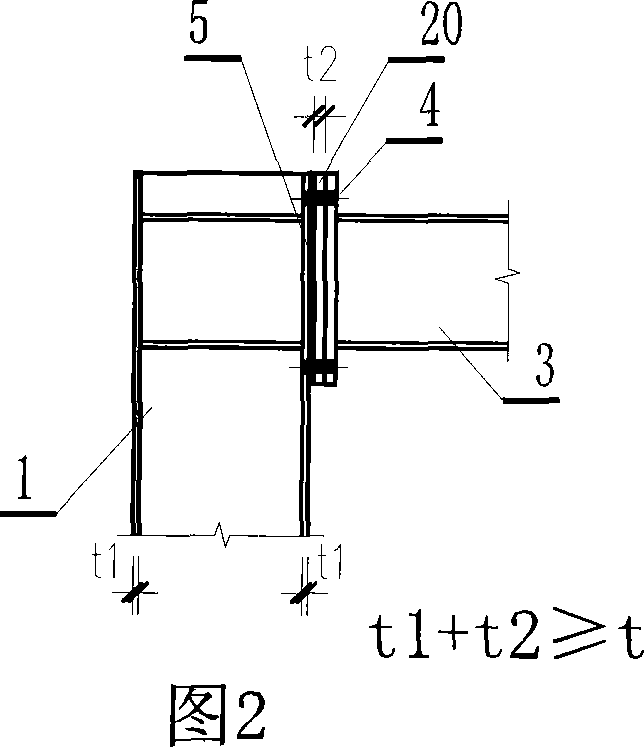
[0016] As shown in Figure 1 and Figure 2, in construction projects, the commonly used column 1 and beam 3 are all welded by three steel plates, and their cross-sectional shape is generally H-shaped. As shown in the prior art, as shown in Fig. 1, the connecting part of the column and the beam needs to be cut and processed into a thickened column flange plate 2, and the column 1 must also be cut into a hole corresponding to the size and shape of the flange plate. Then the thickened flange plate is welded to the column 1 here, and the weld needs to be ultrasonically inspected. The flange plate 2 welded to the column 1 and the end plate 4 welded to the beam 3 are connected with high-strength bolts to connect the column and the beam together. The feature of the present invention is that as shown in Figure 2, the thickened flange plate 20 (t 2 ) And the flange plate (connection part) surface of the steel column 1 should be straight, and then polish the fresh metal surface with a grindin...

example 2

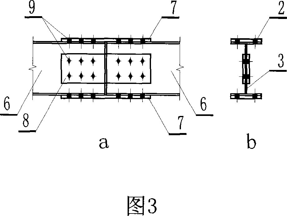
[0018] As shown in Figures 3 and 4, the two beams 6 are also H-shaped members formed by welding three steel plates. In the figure, a represents the schematic diagram of the axial connection of the two beams; in the figure b is the H-shaped schematic diagram of the cross-section of the beam. In the prior art, as shown in Fig. 3, the two steel beams 6 are connected together by flange splicing plates 7, web splicing plates 8, and high-strength bolts 9; the two steel beams 6 can also be connected together by riveting. For the connection of the two beams of the present invention, as shown in FIG. 4, the structural feature is that the flange plate splicing plate 7 and the web splicing plate 8 are directly glued to connect the two steel beams 6 together through the adhesive layer 10. . (The specific implementation method is the same as in Example 1)

example 3

[0020] For areas where the strength of the steel structure of the combined steel plate type is insufficient, reinforcement members are required. In the prior art, as shown in Figure 5, a reinforced steel plate 12 is welded to the insufficient strength of the original steel member 11, and the weld is represented by 13; in the present invention, as shown in Figure 6, the reinforced steel plate 12 is connected to the original steel member by a glue layer 14 11, both convenient and practical (the specific implementation method is the same as that in Example 1).


PUM


Abstract

The invention relates to the architect steel structure glue connecting art. The invention mainly solves the connecting and enforcing of the built-up steel board component that the intersection is H shaped, to improve the produce effect and to decrease the cost. It is characterized in that another steel board is glue connected on the steel component at the location of the built-up steel board connecting location or the enforcing location. For example, the steel board of a thickening flange plate is need to be glue connected on the steel post, the flange splice plate and the web splice plate will glue connect the two H shaped steel bars, the enforcing steel board is glue connected at the enforcing location of the steel component. The invention could be widely used in connecting of the girder, the post and other built-up steel structure components in the architect field.

Description

Technical field [0001] The invention belongs to a method for strengthening the connection of steel components, and relates to the technology of interconnecting steel plate composite components. Background technique [0002] In the construction field, a large number of steel components welded by the combination of steel plates are used, for example, beams and columns with H-shaped cross-sections are welded by three steel plates. The connection between beams and column members often uses high-strength bolts to connect the end plates welded to the beam ends and column flange plates into a structure. The thickness of the beam end plate and the column flange plate of the connection part should generally be equal to or greater than the diameter of the high-strength bolt to ensure their bending and shear strength and rigidity requirements. Therefore, the column flange steel plate welded by the combination of three steel plates needs to be thickened at the connection part, and the thin s...

Claims


Application Information

Patent Timeline
Patent Type & Authority Applications(China)
IPC IPC(8): E04B1/38E04B1/24G01N19/04
Inventor 罗浩邢丽陆俊林峰孙永祥张凯声
Owner HANGZHOU HENGDA STEEL STRUCTURE
Why Eureka
Try Eureka