Charging roller, process cartridge and image forming apparatus
A charging roller and image carrier technology, which can be used in corona discharge devices, electric recording technology using charge patterns, equipment for electric recording technology using charge patterns, etc., and can solve the problems of ion conductive agent leakage, etc.
- Summary
- Abstract
- Description
- Claims
- Application Information
AI Technical Summary
Problems solved by technology
Method used
Image

Examples
Embodiment 1-1
[0110] The calcination temperature in the above-mentioned calcination process was set to "high" among three steps consisting of "high", "standard", and "low". The firing time was set to "long" among three steps consisting of "long", "standard" and "short". The concentration of the surface treatment liquid was set to "high" among three steps consisting of "high", "standard", and "low".
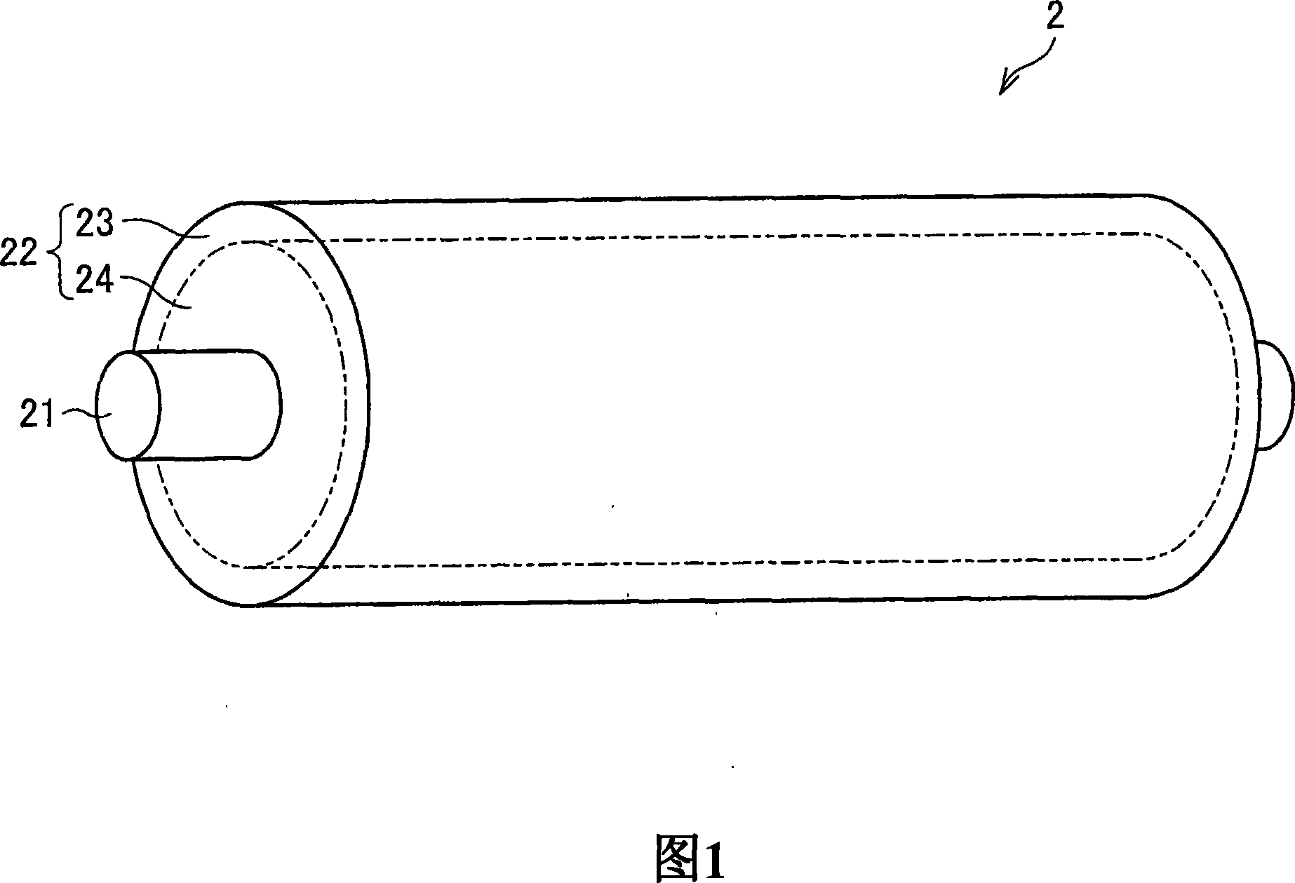
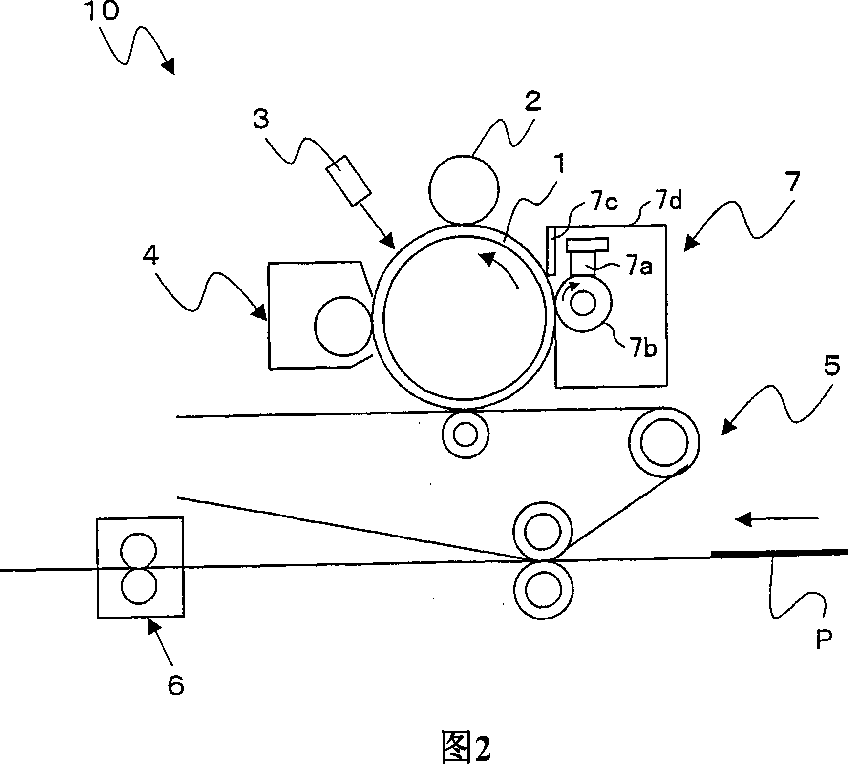
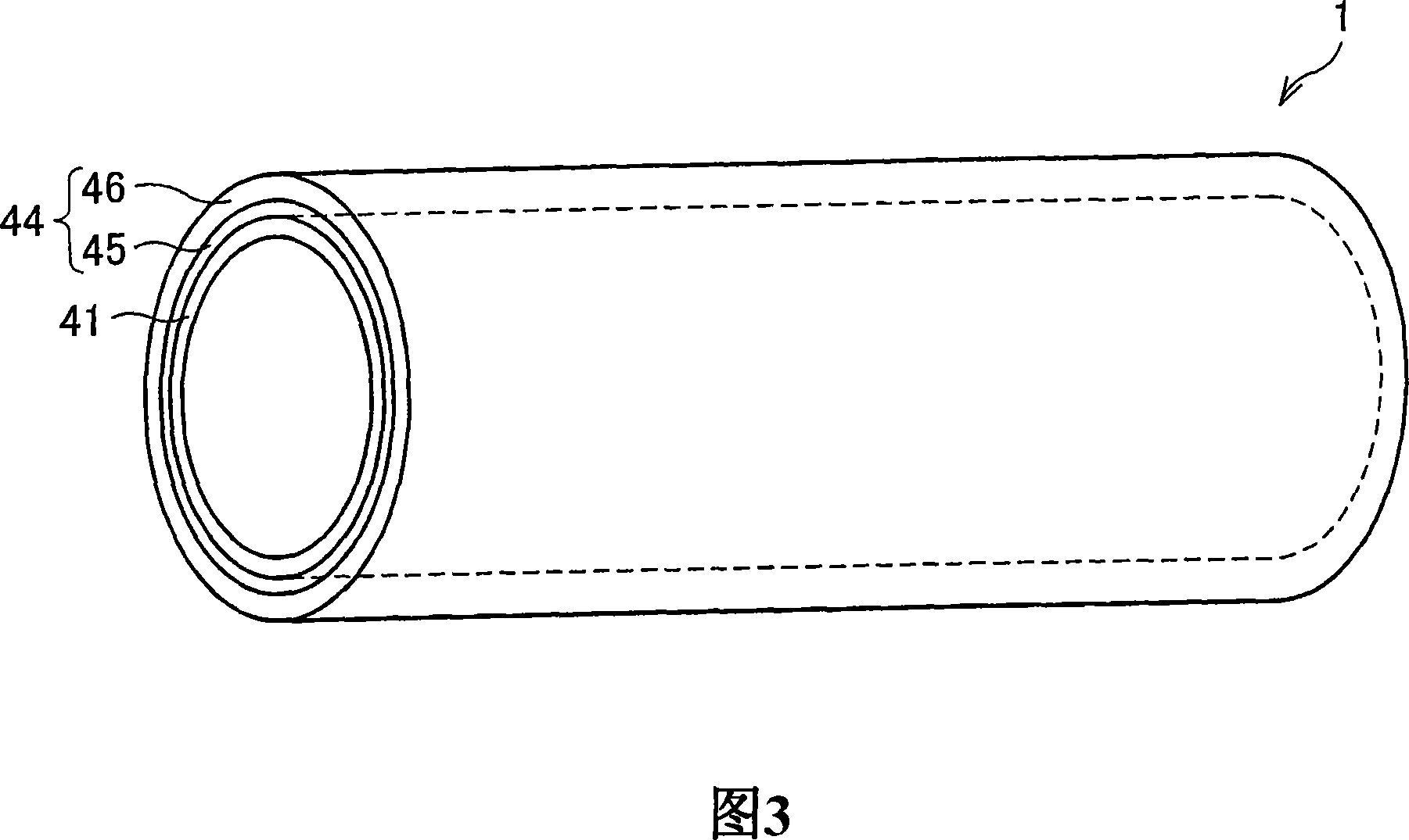
[0111] The charging roller 2 surface-treated under the above-mentioned conditions was brought into contact with the photoreceptor 1 coated with lubricant and stored for a long period of time. As a result, image defects due to contamination of the photoreceptor were not found from the first sheet. Also, the coefficient of dynamic friction between the charging roller 2 and the photoreceptor 1 is 0.25.
[0112] However, after the charging roller 2 was assembled into the modified equipment for printing, black streak-like image defects were obviously found. This is considered to be because the sli...
Embodiment 1-2
[0114] The firing temperature was set to "high", the firing time was set to "long", and the concentration of the surface treatment liquid was set to "high".
[0115] The charging roller 2 surface-treated under the above conditions was brought into contact with the photoreceptor 1 not coated with lubricant and stored for a long period of time. As a result, image defects due to contamination of the photoreceptor were not found from the first sheet. Also, the coefficient of dynamic friction between the charging roller 2 and the photoreceptor 1 is 0.25.
[0116]However, after printing with the charging roller 2 , a small amount of image defects in the form of black streaks were found. It is considered that this is because the charging roller 2 slightly slipped.
Embodiment 1-3
[0118] The calcination temperature was set as "high", the calcination time was set as "long", and the concentration of the surface treatment liquid was set as "standard".
[0119] The charging roller 2 surface-treated under the above-mentioned conditions was brought into contact with the photoreceptor 1 not coated with lubricant and stored for a long period of time. As a result, image defects due to contamination of the photoreceptor were not found from the first sheet. Also, the coefficient of dynamic friction between the charging roller 2 and the photoreceptor 1 was 0.27. Further, even after printing was performed with this charging roller 2 , no image defect due to slipping of the charging roller 2 was found.
PUM
 Abstract
Description
Claims
Application Information
PatSnap Eureka turns technology decisions into work you can execute. Powered by our Innovation Knowledge Graph, it runs expert workflows across engineering, life sciences, materials and intellectual property. Get your review-ready output in minutes.


