
Low-voltage high-voltage generated three-phase asynchronous motor DC power generation system

A three-phase asynchronous, power generation system technology, applied in asynchronous induction motors, control systems, AC motor control, etc., can solve problems such as high technical content, high difficulty, and difficult implementation

Inactive Publication Date: 2007-10-31
NANJING UNIV OF AERONAUTICS & ASTRONAUTICS
View PDF0 Cites 10 Cited by
  • Summary
  • Abstract
  • Description
  • Claims
  • Application Information

AI Technical Summary

Problems solved by technology

[0003] Although the asynchronous motor essentially has the ability of reversible operation of motoring / generating, the working conditions of the same motor are often quite different in motoring and generating operation, which makes it difficult to design a dual-function system of starting / generating. In: when starting, the motor is in the low-speed area below the ignition speed of the generator, and the power supply is usually low voltage (such as 48V battery); the motor works at high current and outputs high torque; when generating power, the motor is at a speed much higher than the ignition speed of the engine In the high-speed area, it is required to meet the high-quality requirements of power supply dynamic and static, and the system power generation voltage is high voltage (such as 270V high-voltage DC), which are often contradictory
Therefore, the starting / generating dual-function system is different from the general electric / generating reversible operation, and has high technical content and is difficult to realize.

Method used


Image

  • Low-voltage high-voltage generated three-phase asynchronous motor DC power generation system
  • Low-voltage high-voltage generated three-phase asynchronous motor DC power generation system
  • Low-voltage high-voltage generated three-phase asynchronous motor DC power generation system

Examples


Embodiment Construction

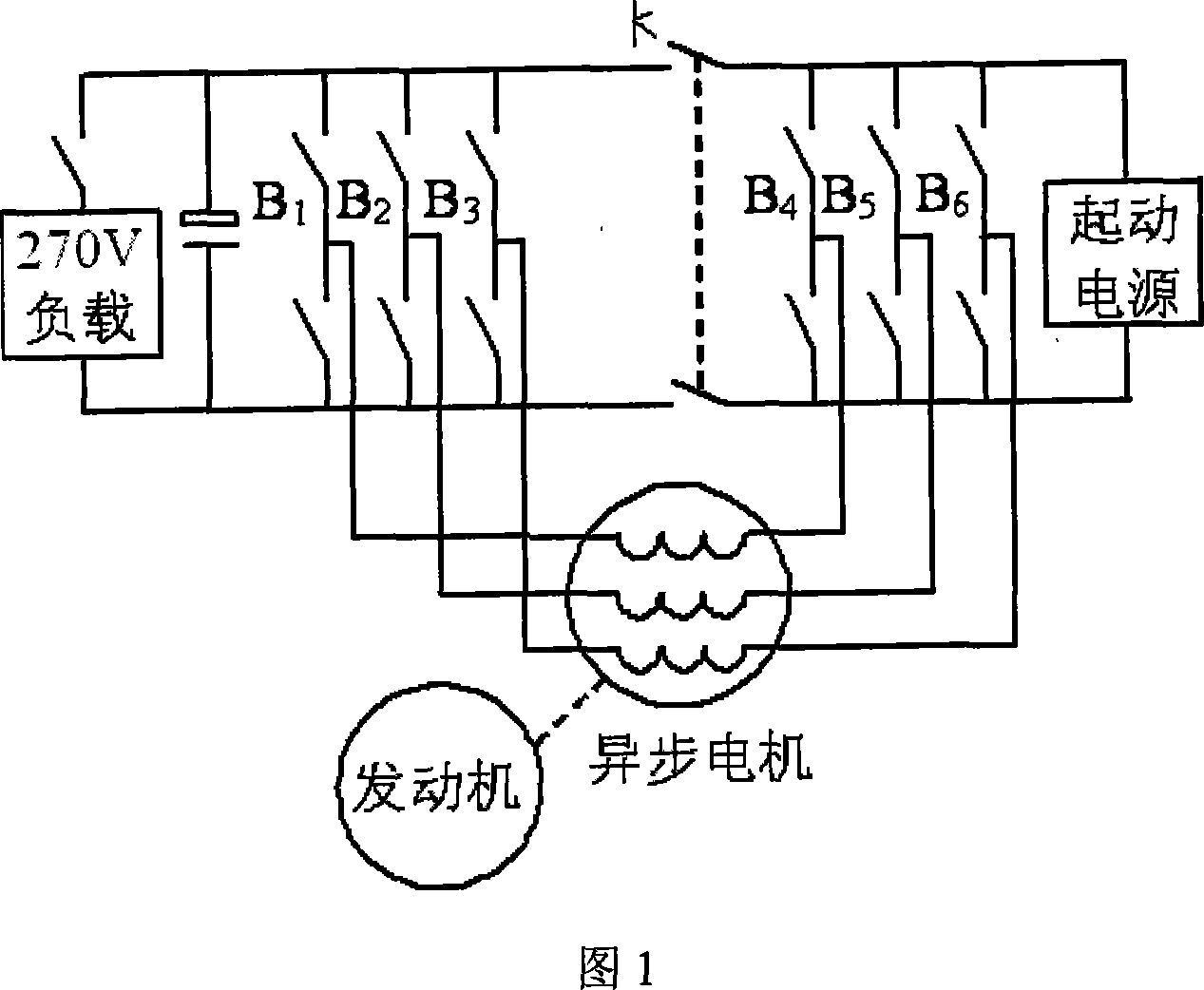
[0016] Accompanying drawing 1 is the topological structure schematic diagram of main circuit of the present invention, and the structure of this circuit includes asynchronous motor, starting power supply and main loop power switching converter. The main circuit power switching converter includes two three-phase inverter bridges, and the three-phase inverter bridge on the left side of the circuit is controlled by the first bridge arm B 1 , the second bridge arm B 2 and 3rd arm B 3 Composed of three bridge arms, the three-phase inverter bridge takes the DC bus as the output and connects to the load to supply high-voltage DC power. The midpoints of the three bridge arms are connected to the three outlets at one end of the three-phase winding of the asynchronous motor; the circuit on the right The three-phase inverter bridge on the side consists of the fourth bridge arm B 4 , 5th bridge arm B 5 and 6th arm B 6 Composed of three bridge arms, the DC bus of the three-phase invert...


PUM


Abstract

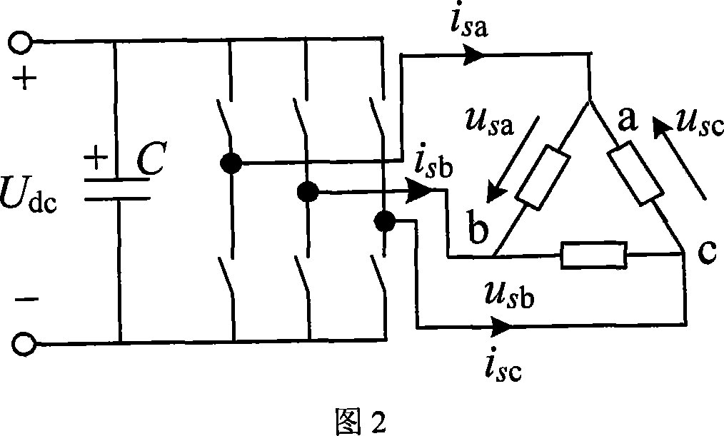
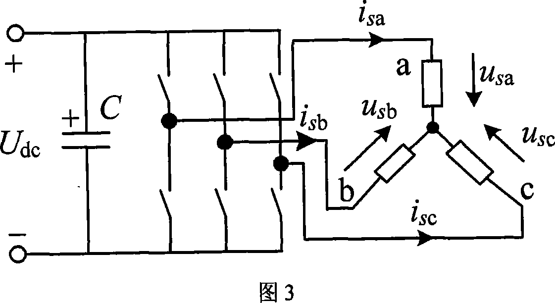
A kind of three-phase asynchronism motor direct current starting generate electricity system that is started in low voltage and generates electricity in high voltage includes three phase asynchronism motor, starting power source and main loop power switch converter, it characterized in that said main loop power switch converter includes two three-phase inversion bridges, thereinto the midpoint of three bridge arms of three-phase inversion bridges whose one direct current generatrix is connected with the starting power source is connected with three leading-out terminals of three-phase winding of asynchronism motor, the midpoint of three bridge arms of three phase inversion bridges whose another direct current generatrix is connected with the starting power source is connected with three leading-out terminals of three-phase winding in another side of asynchronism motor, power switch composes connection of starting in low voltage 'Delta', connection of generating in high voltage 'Y', direct current generatrix of two three-phase inversion bridges are parallel connected with conversion switch, the starting running is parallel connected, generating running is cut off. The system resolves contradiction of starting in low voltage and generating in high voltage, and applied in independent power system such as avigation, chariot, and shipping.

Description

1. Technical field [0001] The asynchronous motor high-voltage direct-current starting power generation system of the present invention belongs to a starter / generator, and is applied to independent power systems such as aviation, chariots, and ships. 2. Background technology [0002] A key component in a starter / generator dual-function system is the motor. Currently, there are types of motors such as brushless synchronous motors, switched reluctance motors, and asynchronous motors that are being developed as starter-generator motors. Among them, the cage-type asynchronous motor has a solid and reliable structure, is easy to maintain, and can run at high speed. The dual-function system of starting / generating based on asynchronous motors has attracted more and more attention. From 1997 to 2000, experts and some scholars from the NASALewis Research Center in the United States continuously wrote articles in IEEE magazines and conferences based on the research results of the previ...

Claims


Application Information

Patent Timeline
IPC IPC(8): H02K17/30H02K17/42H02P27/06
Inventor 黄文新胡育文
Owner NANJING UNIV OF AERONAUTICS & ASTRONAUTICS
Learn More