
Moving picture coding method and moving picture coding apparatus

An image decoding and image technology, which is applied in the field of decoding, can solve the problems that the size of the storage area cannot be determined, the maximum size of the reference candidate image is not set, and the maximum size cannot be set.

Inactive Publication Date: 2007-10-31
GK BRIDGE 1
View PDF0 Cites 4 Cited by
  • Summary
  • Abstract
  • Description
  • Claims
  • Application Information

AI Technical Summary

Problems solved by technology

[0041] In this way, a plurality of decoded or coded images are stored in the image memory of the decoding device or encoding device, but so far, in the H.264 mode, no inter-image predictive coding and image Restrictions on the maximum number of reference candidate pictures (maximum reference candidate pictures) used in inter-picture predictive decoding
[0042] Therefore, in the design of the encoding device and decoding device corresponding to the H.264 method, it is impossible to set the maximum size of the decoded or encoded image that should be stored in the image memory, and it is impossible to determine the maximum size of the image that should be loaded in the image memory. The size of the capacity of the storage area on the device

Method used


Image

  • Moving picture coding method and moving picture coding apparatus
  • Moving picture coding method and moving picture coding apparatus
  • Moving picture coding method and moving picture coding apparatus

Examples


Embodiment 1

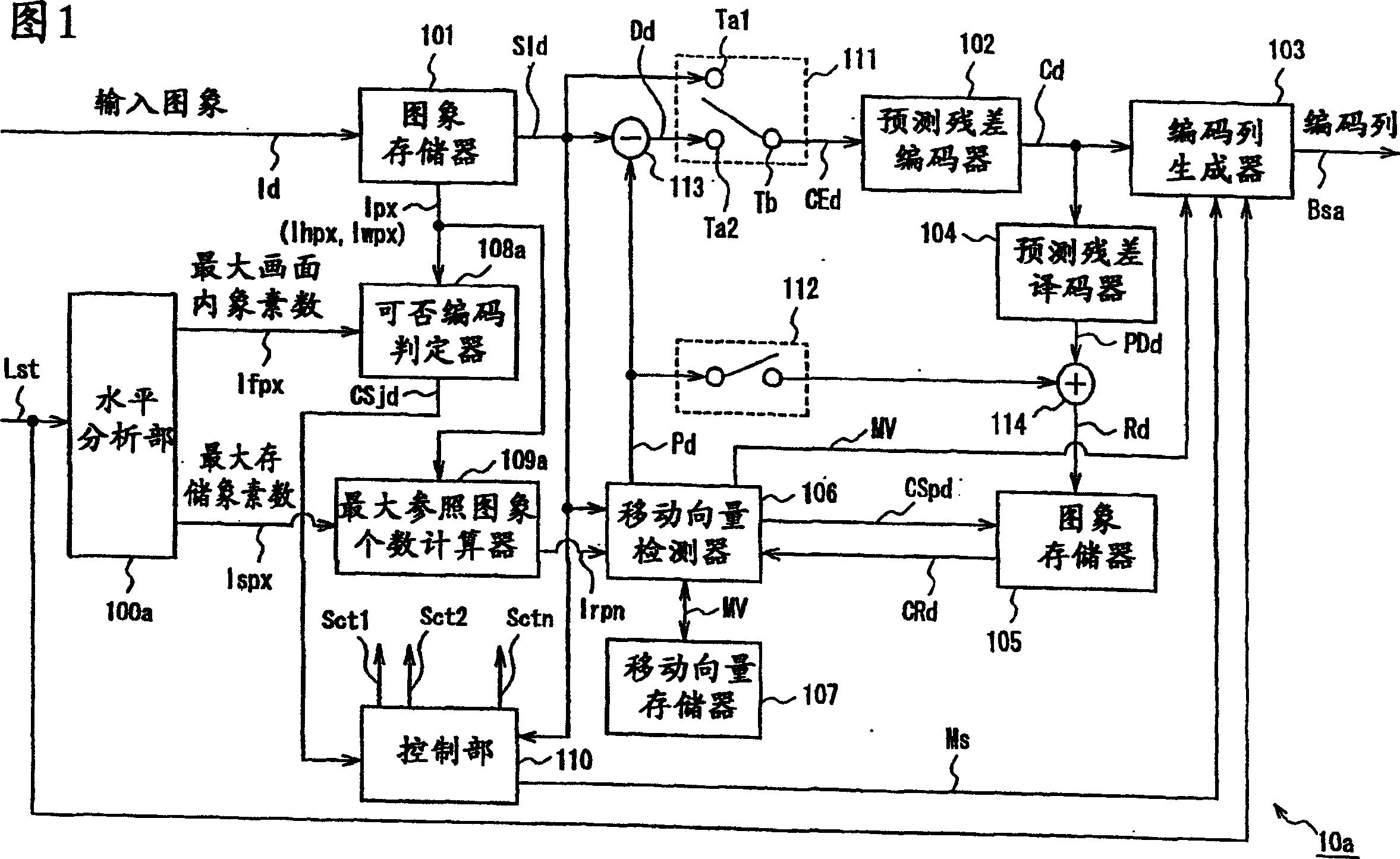
[0181] Fig. 1 is a block diagram illustrating a moving image coding apparatus 10a according to Embodiment 1 of the present invention.

[0182] The moving picture encoding device 10a of the first embodiment divides a plurality of pictures constituting a moving picture into predetermined data processing units (blocks), and encodes the picture data of each picture for each block. Here, the block is a macro block having 16 pixels in the vertical and horizontal directions.

[0183] That is, the animation image encoding device 10a includes: store the data (input data) Id of an animation image (input image) input by each image, and output the stored data SId by each block; The differential calculator 113 that calculates the difference data between the image data SId of the target block to be coded and the prediction data pd of the target block outputted from the image memory 101 as the prediction error data Dd of the target block; The image data SId or the prediction error data Dd a...

Embodiment 2

[0261] Fig. 4 is a block diagram illustrating a moving image coding apparatus 10b according to Embodiment 2 of the present invention.

[0262] The animation image encoding device 10b of Embodiment 2 of the present invention replaces the level analysis unit 100a and the encoding availability determiner 108a of the animation image encoding device 10a of Embodiment 1, including: according to the input level signal Lst and the identification number signal Cid, output The horizontal analysis unit 100b of the maximum in-screen pixel number information Ifpx, the maximum stored pixel number information Ispx, and the pixel calculation coefficient information αpx; based on the maximum in-screen pixel number information Ifpx, the pixel calculation coefficient information αpx and the input image As for the image size information Ipx, the encoding availability determiner 108b determines whether the input image can be encoded. Here, the identification number signal Cid indicates the value o...

Embodiment 3

[0309] Fig. 6 is a block diagram illustrating a moving image coding apparatus 10c according to Embodiment 3 of the present invention.

[0310] The moving image encoding device 10c of the present embodiment 3 replaces the level analysis unit 100a and the encoding availability determiner 108 of the moving image encoding device 10a of the embodiment 1, and includes: outputting the largest picture according to the input level signal Lst and the identification encoding signal Sid The horizontal analysis section 100c of the information on the number of pixels Ifpx, the information Ispx on the number of pixels stored at the maximum, and the information (maximum image size information) Impx representing the maximum image size; The information Impx and the input image size information Ipx are used to determine whether the input image can be encoded or not by the encoding possibility determiner 108c.

[0311] Here, the identification coding signal Sid represents the value of the identif...


PUM


Abstract

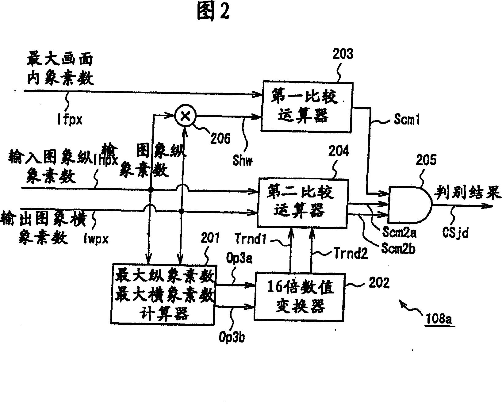
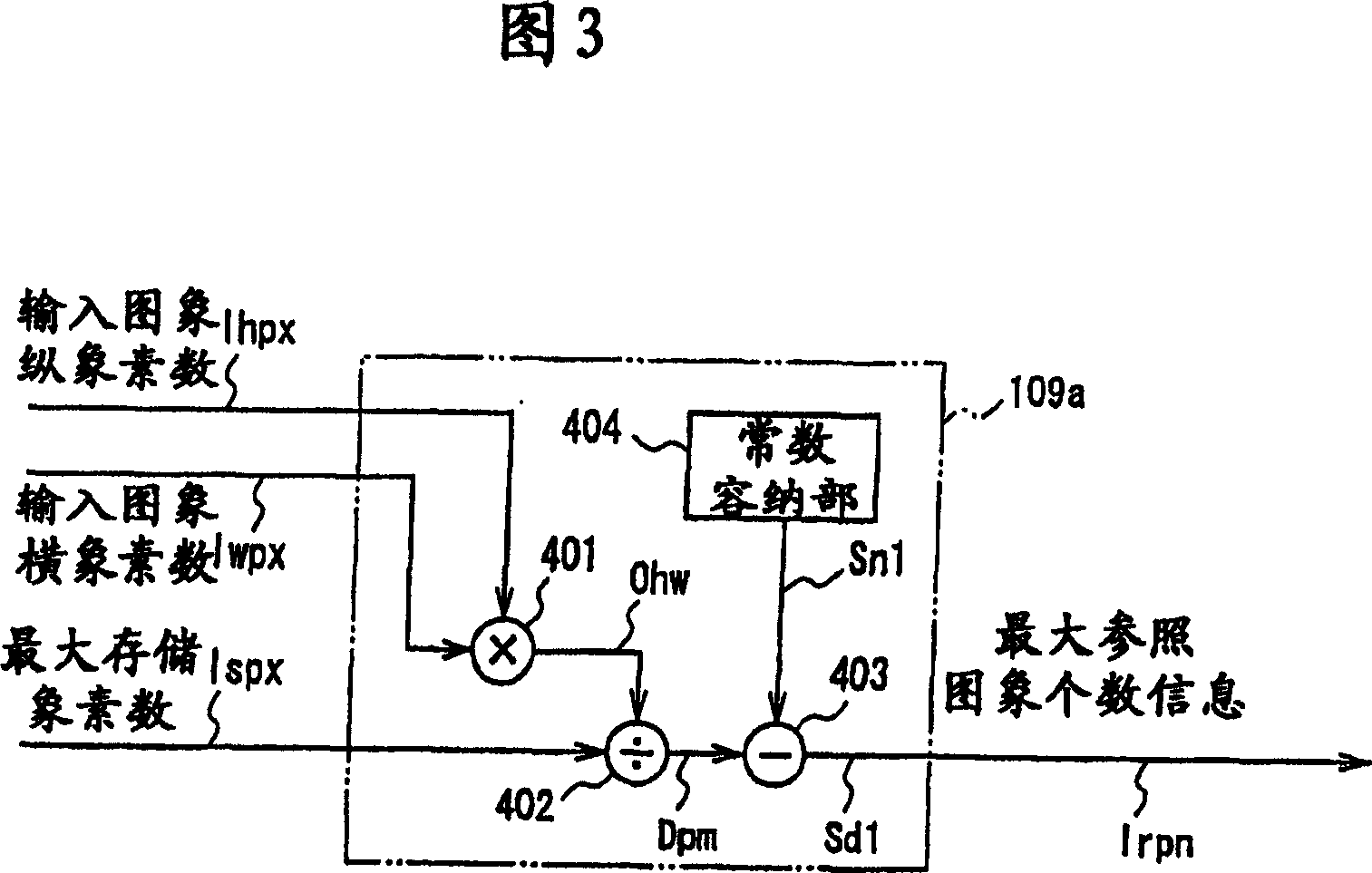
The invention provides a moving image coding method and a moving image coding device. The moving image coding device (10a) comprises a level analyzer (100a) that determines the maximum number of codable on-screen pixels (Nfpx) based on a level identifier (Lst) indicating a user-specified coding level and the maximum number of stored pixels (Nspx) that can be stored in the picture memory of a decoding device. Based on the maximum number of on-screen pixels (Nfpx) and an input image size (number of vertical pixels (Nhpx) and number of horizontal pixels (Nwpx)), the moving image coding device (10a) determines i f an input image can be coded and, at the same time, calculates the maximum number of reference pictures (Nrpn) that is the number of reference candidat e pictures that can be referenced during inter-picture predictive coding. A decoding device, which receives a code string from such a moving picture coding device (10a), can always decode the code string properly and can perform inter-picture predictive decoding corresponding to inter-picture predictive coding on the coding side. As a result, it is possible to design the memory area of a coding device and a decoding device compatible with a coding method that does not limit the capacity of the memory area.

Description

[0001] This application is a divisional application of the invention whose application number is "03800107.1", the filing date is January 31, 2003, and the title of the invention is "animated image coding method and animated image decoding method". technical field [0002] The present invention relates to an animation image encoding method and an animation image decoding method, in particular to an encoding method for encoding digital data of an animation image for transmission or storage and a decoding method corresponding to the encoding method. Background technique [0003] An animation image is composed of a plurality of images, and the image is composed of a given number of pixels. Furthermore, the coding of moving pictures is performed for each of the above-mentioned pictures, and the coding of each picture is performed in units of blocks dividing the picture. [0004] Generally, in the encoding of moving pictures, the amount of information is compressed by reducing re...

Claims


Application Information

Patent Timeline
Patent Type & Authority Applications(China)
IPC IPC(8): H04N7/50H04N7/26H04N7/36G06T9/00H04N19/172H04N19/423H04N19/503H04N19/61
Inventor 安倍清史角野真也羽饲诚近藤敏志
Owner GK BRIDGE 1
Learn More