Car door frame edge binding process and mold
A process method and frame wrapping technology, applied in the direction of forming tools, manufacturing tools, metal processing equipment, etc., can solve the problems of reducing precision, achieve the effects of improving production efficiency, ensuring processing accuracy, and shortening operation time
- Summary
- Abstract
- Description
- Claims
- Application Information
AI Technical Summary
Problems solved by technology
Method used
Image

Examples
Embodiment
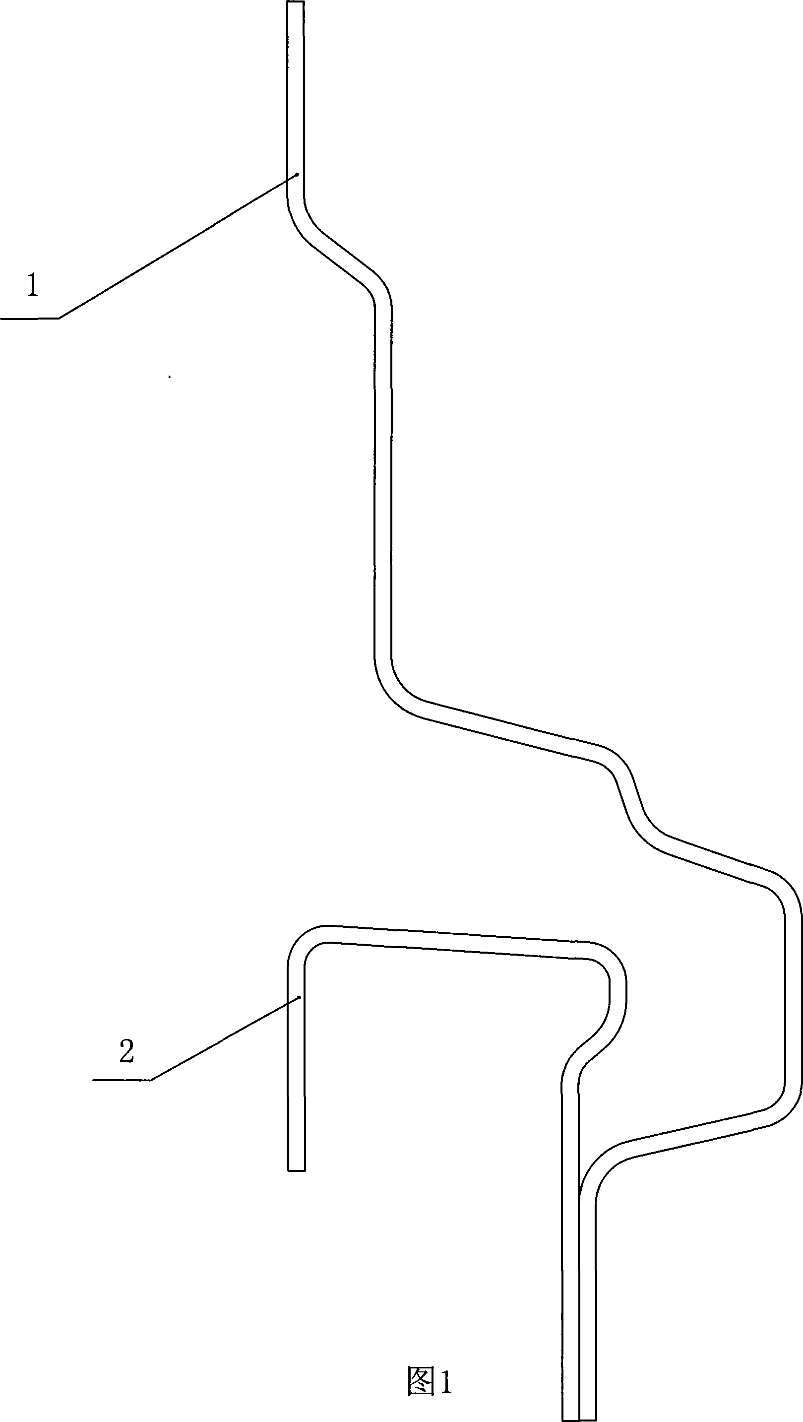
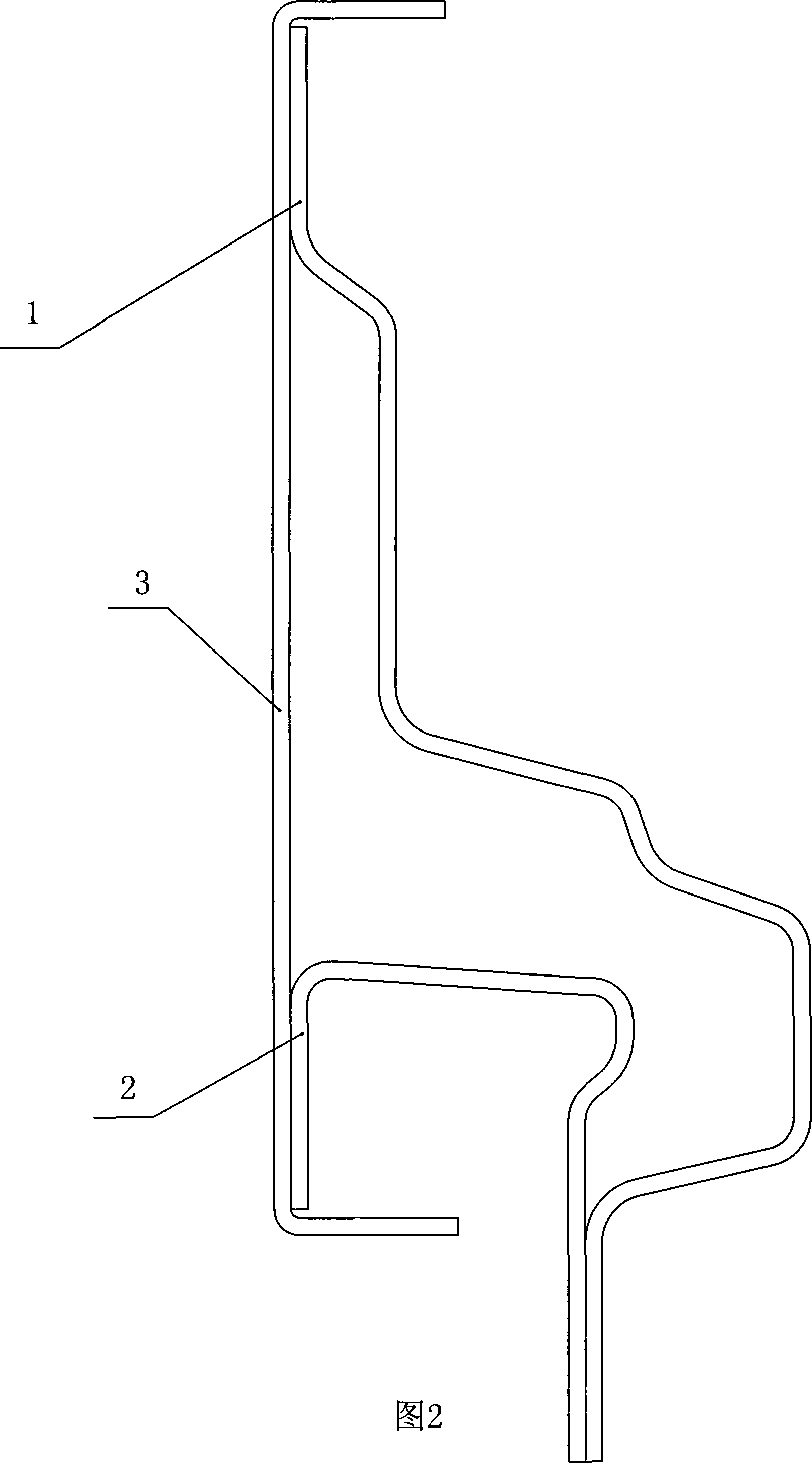
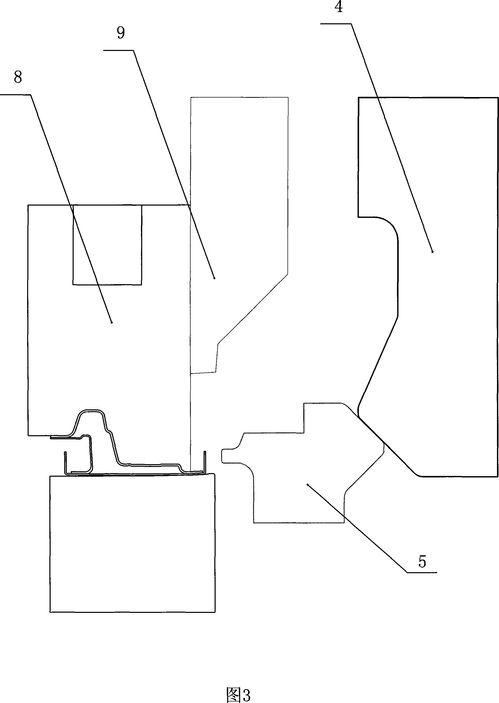
[0026] Embodiment: A kind of car door frame wrapping die comprises upper mold and lower mold, and upper mold is provided with binder plate 8, and the shape of binder plate matches with the inner panel 1 after stamping, and the edge of binder plate is provided with Punch 9, the head of the punch matches the edge of the outer plate 3, a block 4 is provided on the side of the punch, and a slider 5 is provided on the side of the inner plate at the corresponding height of the outer plate of the lower die. Can do horizontal movement, the inner side of the block is a curved surface, the shape of the curved surface is consistent with the movement track of the slider, the slider is equipped with a tension spring, the tension spring makes the slider and the inner curved surface of the block always fit, the slider is playing Driven by the block, there is an oil cylinder slider near the side of the guide rail. The end size of the oil cylinder slider is smaller than the vertical height of t...
PUM
 Abstract
Description
Claims
Application Information