
Offset press

A technology for printing presses and offset plates, applied in the field of operating offset printing presses, can solve problems such as troublesome adjustment mechanisms, and achieve the effects of eliminating vibration, short response time, high acceleration and moving speed

Inactive Publication Date: 2010-08-04
SCHAEFFLER TECH AG & CO KG
View PDF5 Cites 0 Cited by
  • Summary
  • Abstract
  • Description
  • Claims
  • Application Information

AI Technical Summary

Problems solved by technology

Overall, the offset printing press known from DE 102 09 536 A1 has a very cumbersomely constructed adjustment mechanism

Method used


Image

  • Offset press
  • Offset press
  • Offset press

Examples


Embodiment Construction

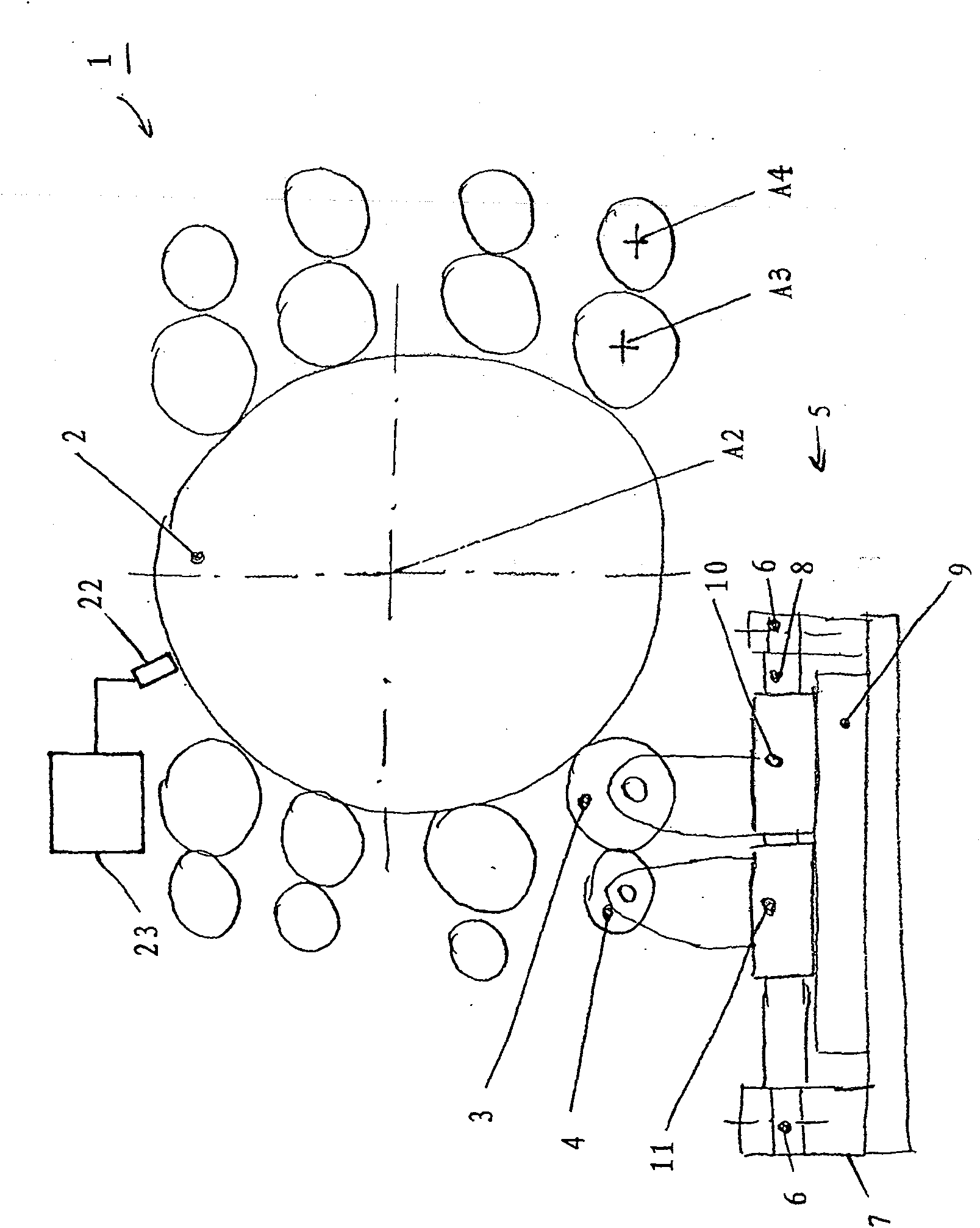
[0016] figure 1 The basic functional elements of the offset printing machine 1 are schematically shown. A central support roller 2 cooperates with the format roller 3 and the ink roller 4 . A not shown web of material to be printed bears against the surface of the support roller 2 . The format roll 3, which presses the material web against the support roll 2, has a printed sample on its surface. Printing ink is transferred from ink roller 4 to format roller 3 . In the exemplary embodiment shown, there are eight pairs each consisting of a format roller 3 and an ink roller 4 .

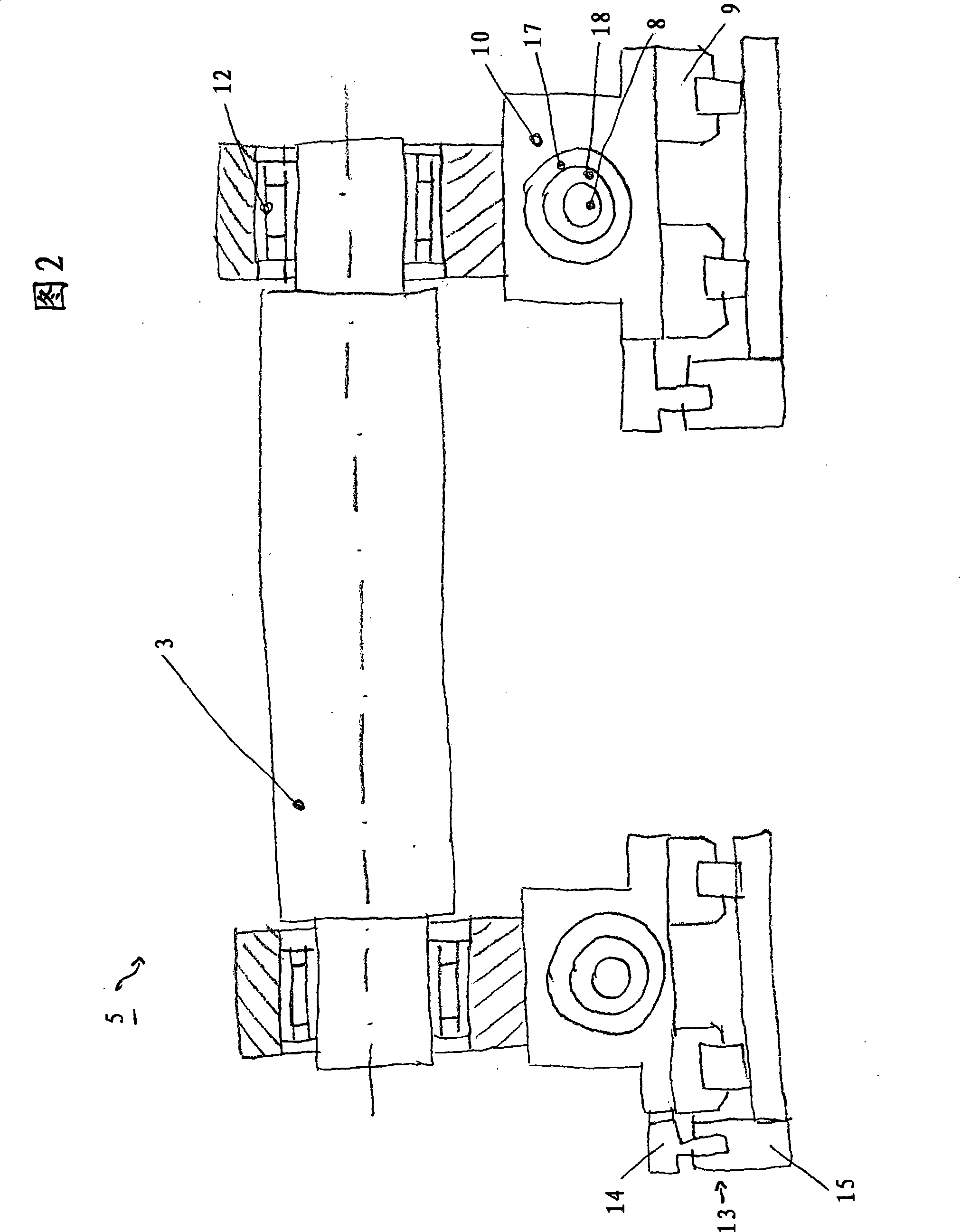
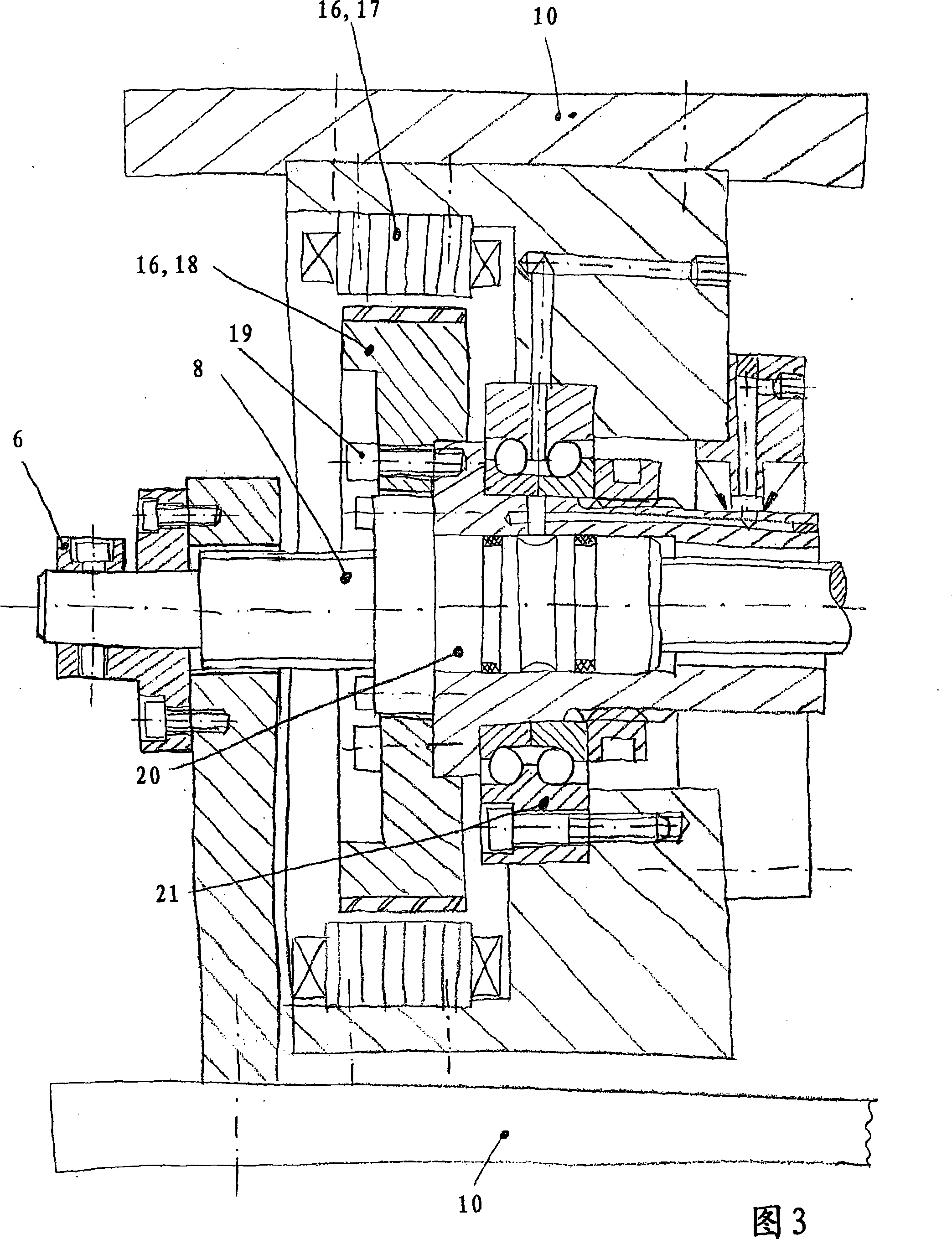
[0017] Both the format roller 3 and the ink roller 4 can be replaced when necessary. In order that each individual axis A3 of the format roller 3 and each axis A4 of the ink roller 4 can be adjusted relative to the axis A2 of the backup roller 2 , each pair of rollers 3 , 4 has a displacement device 5 . The displacement device 5 has a fixed spindle 8 , which is arranged on a frame 7 , for example by...


PUM


Abstract

A flexographic print machine has a counter-pressure cylinder (2) surrounded by several pairs of format cylinders (3) and color cylinders (4). The format cylinder contacts both the counter-pressure cylinder (2) and the color cylinder (4). A moving mechanism (5) adjusts the format- and color cylinder axle (A3, A4) positions with respect to the counter-pressure cylinder axle (A2). The moving mechanism (5) includes a fixed-position spindle (8) with respect to the counter-pressure cylinder axle (A2). The spindle thread nut (20) guides two independently operating riders (10, 11), that move the format cylinder (3) and color cylinder (4), on the spindle (8). Wherein a rotor (18)of a motor for directly driving the spindle thread nut (20) is fixed jointed with the spindle thread nut (20).

Description

technical field [0001] The invention relates to an offset printing machine (flexodruck machine) which has a central support roll and format and ink rollers surrounding the central support roll. Furthermore, the invention relates to a method of operating an offset printing press. Background technique [0002] An offset printing press is known, for example, from DE 102 09 536 A1. Offset printing presses of this type have supports on both sides of a vertical center plane extending through the shafts of the support rollers, on which supports various rolling bearing bearings are arranged displaceably. The movability of the roller bearing supports enables the inking roller or format roller, also known as printing roller, to be replaced if necessary, for example after a changeover of printing jobs. Movement of the individual rolling bearing supports is achieved by means of various spindles and gear belt drives. Overall, the offset printing press known from DE 102 09 536 A1 has a...

Claims


Application Information

Patent Timeline
Patent Type & Authority Patents(China)
IPC IPC(8): B41F13/34B41F13/20B41F13/008B41F33/08
CPCB41F5/24B41F13/38B41F13/30
Inventor B·森格尔G·施密德P·西布克S·扎姆索A·克劳斯M·A·希门尼斯
Owner SCHAEFFLER TECH AG & CO KG
Learn More