Supercharge Your Innovation With Domain-Expert AI Agents!

Projecting device

一种投影装置、影象的技术,应用在照明装置、放映装置、摄影等方向,能够解决泄漏、不能遮挡等问题

Active Publication Date: 2007-11-07
SANYO ELECTRIC CO LTD
View PDF1 Cites 10 Cited by
  • Summary
  • Abstract
  • Description
  • Claims
  • Application Information

AI Technical Summary

Problems solved by technology

[0006] However, the above-mentioned method cannot block the light indicated by the dotted arrow in Fig. 13 and Fig. 14 among the outgoing light emitted by the lamp unit (4), and cannot completely prevent the light of the lamp unit (4) from coming out of the housing. vent leak

Method used


Image

  • Projecting device
  • Projecting device
  • Projecting device

Examples


Embodiment Construction

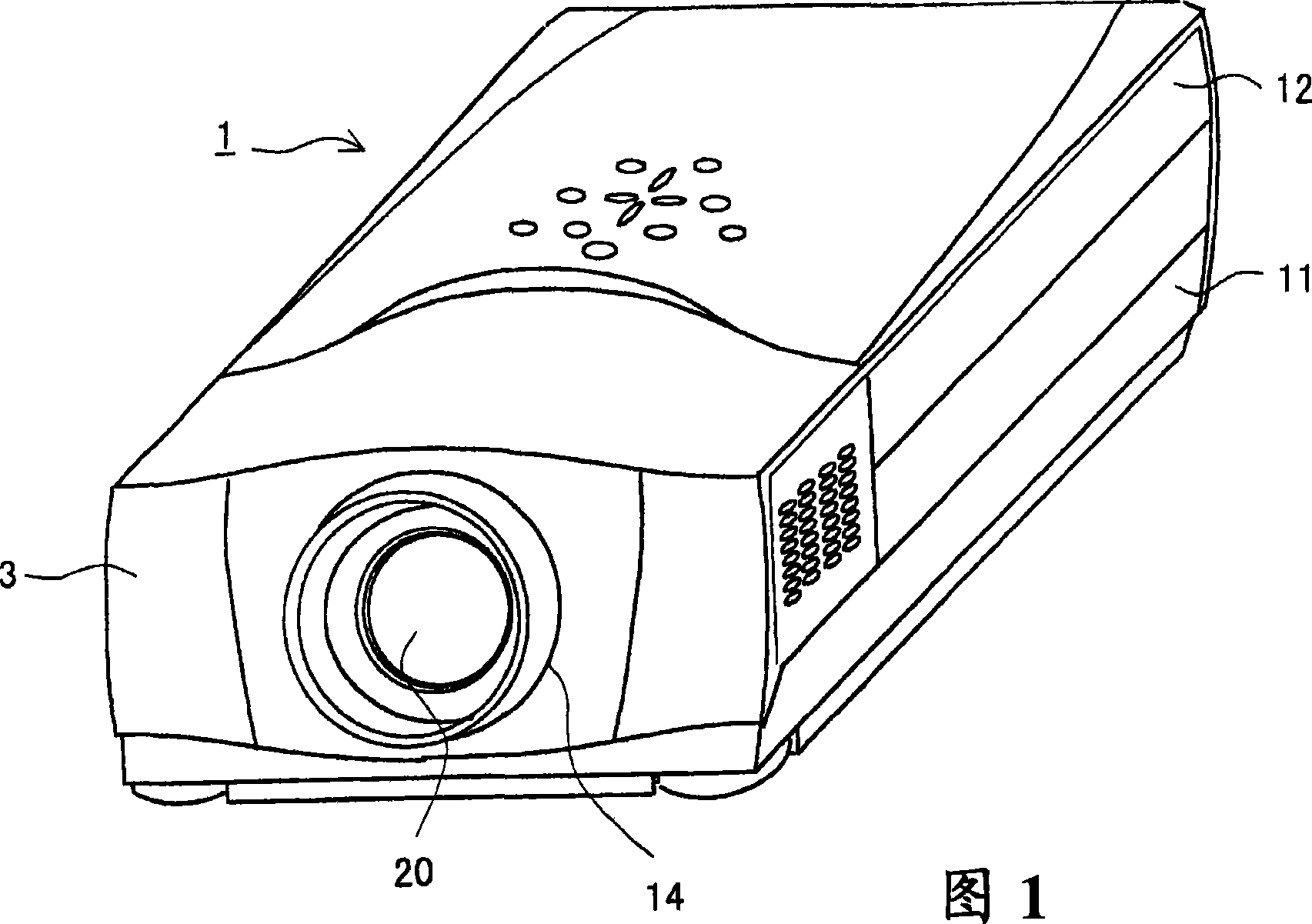
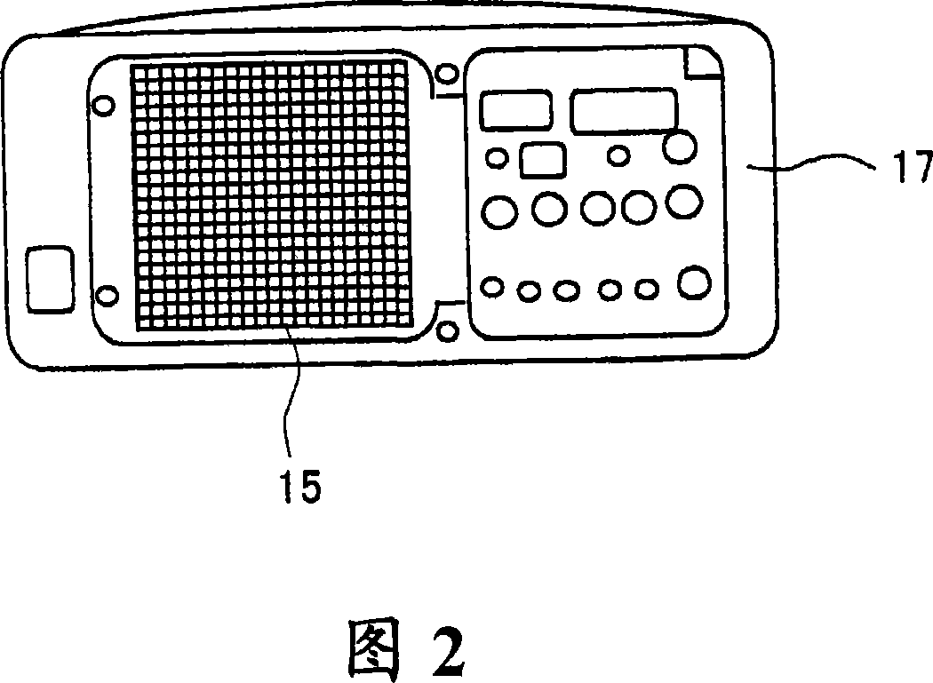
[0055] Hereinafter, the manner in which the present invention is implemented in a liquid crystal projection device will be described in detail with reference to the accompanying drawings. As shown in Figure 1, the liquid crystal projection device has a flat shell (1) made of a lower half shell (11) and an upper half shell (12). On the front panel (13) of the shell (1), there is a projection windows (14). In addition, as shown in FIG. 2 , vent holes used as vent holes ( 15 ) are opened on the rear panel ( 17 ).

[0056] Inside the housing (1), as shown in FIG. 3, there are an optical unit (2) for generating color image light, and a lamp unit (4) as a light source for the optical unit (2). In addition, the lamp unit (4) is accommodated in the outer holder (7).

[0057] optical unit

[0058]As shown in Figure 4, in the optical unit (2), the white light incident from the lamp unit (4) on the first field reflector (フイ-ルドミラ-) (21) is reflected by the first field reflector (21) R...


PUM


Abstract

A projector device-of the present invention includes a light blocking mechanism for blocking leak light from a lamp unit. The light blocking mechanism includes a first light blocking member having a plurality of first light blocking plates arranged therein at certain pitches, and a second light blocking member having a plurality of second light blocking plates arranged therein at certain pitches. The first light blocking plates and the second light blocking plates each define a gap providing an air flow passage. A flat inclined part of each second light blocking plate extends in an inverted direction to a flat inclined part of each first light blocking plate, with a predetermined angle of inclination, so that the first light blocking plates and the second light blocking plates block the light emitted from the lamp unit toward a vent of a casing in all orientations.

Description

technical field [0001] The present invention relates to a projection device that guides light from a light source into an optical system to generate an image and enlarges it to project on a front screen. Background technique [0002] As a projection device, an optical unit for generating an image and a lamp unit as a light source for the optical unit are provided in a housing. The lamp unit will generate heat when it emits light. If the temperature of the lamp unit exceeds the limit temperature, the life of the lamp unit will be shortened. Therefore, the lamp unit must be air-cooled by cooling air. [0003] As shown in Figure 15, the lamp unit (4) is accommodated in the holder (71), and the holder (71) is provided with hot air for cooling the lamp unit (4) inside the holder (71). Exhaust to the air hole (72) outside the holder (71). Furthermore, the casing is provided with exhaust holes for exhausting the hot air exhausted from the holder (71) to the outside. [0004] In ...

Claims


Application Information

Patent Timeline
Patent Type & Authority Applications(China)
IPC IPC(8): G03B21/16G03B21/00F21Y101/00
CPCG03B33/12G03B21/2026G03B21/16
Inventor 南和哉宫本正昭
Owner SANYO ELECTRIC CO LTD
Features
  • R&D
  • Intellectual Property
  • Life Sciences
  • Materials
  • Tech Scout
  • Unparalleled Data Quality
  • Higher Quality Content
  • 60% Fewer Hallucinations
Learn More