
Swivel device

A technology of swivel and sealing device, which is applied in the direction of engine sealing, adjustable connection, pipe/pipe joint/pipe fitting, etc., and can solve the problem of high cost

Inactive Publication Date: 2007-11-07
FRAMO ENG
View PDF0 Cites 1 Cited by
  • Summary
  • Abstract
  • Description
  • Claims
  • Application Information

AI Technical Summary

Problems solved by technology

This also results in high costs since the manufacturing process via the swivel has to be stopped during this period

Method used


Image

  • Swivel device
  • Swivel device
  • Swivel device

Examples


Embodiment Construction

[0022] To facilitate the understanding of the present invention, equivalent reference numerals are used for equivalent elements throughout the drawings.

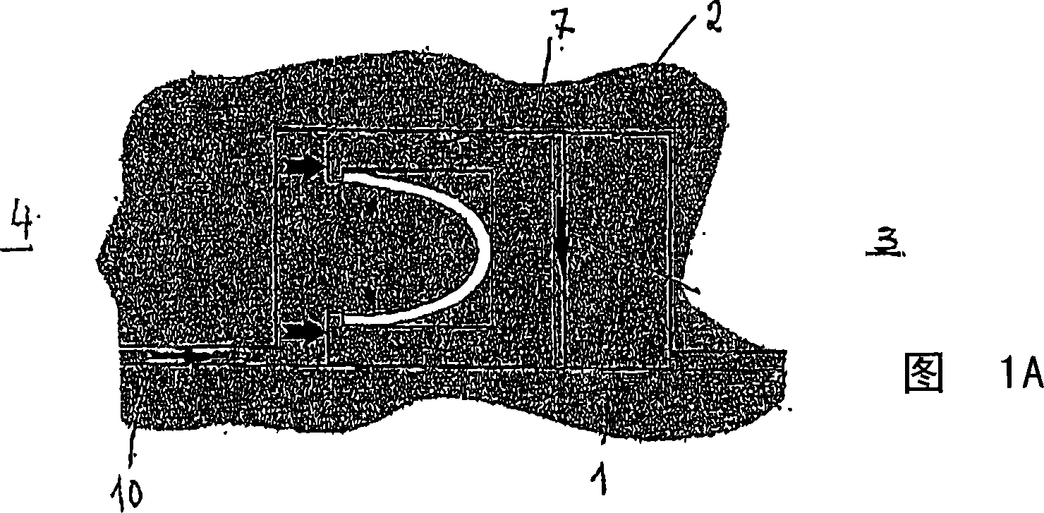
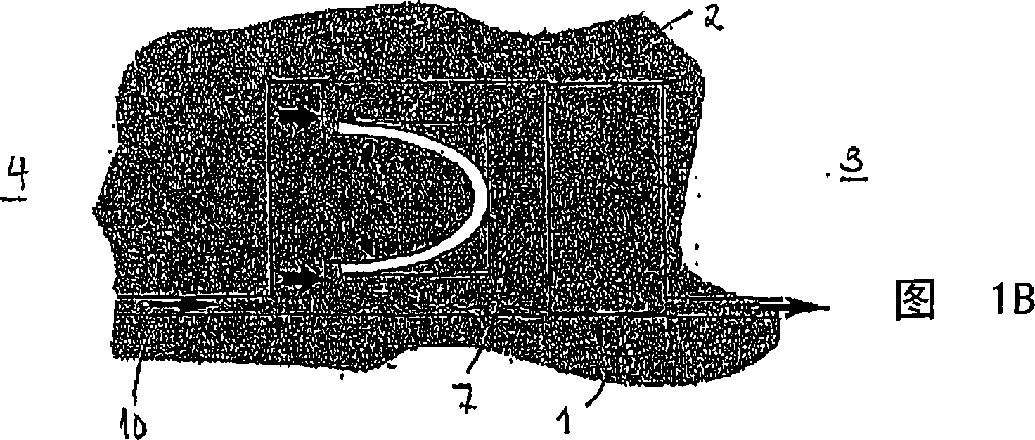
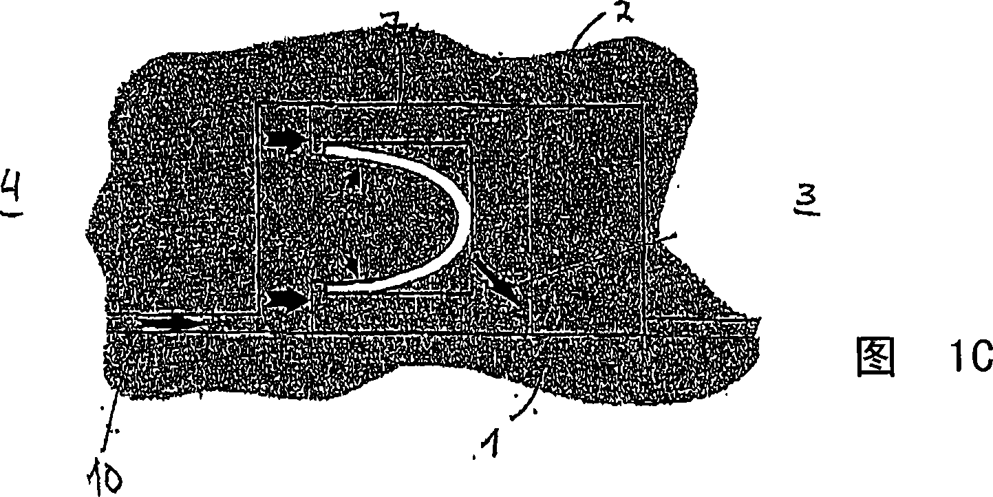
[0023] Figures 1A-1C illustrate the three main principles of how barrier pressure operated dynamic seals leak. The seal is located between two opposing surfaces, one of which comprises a first element 1 , which may be a rotating element, and a second element 2 , which may be a stationary element. The sealing device comprises a sealing body 7 . In the embodiment shown, the sealing body 7 is designed such that the barrier fluid supplied via the supply line 10 forces the sealing body 7 into abutment against the first and second elements 2, respectively. The seal is located between the process channel 3 and the environment 4 . As shown in FIG. 1A , leakage can occur between the sealing body 7 and the surface of the second element 2 , thereby preventing fluid from leaking through the sealing body 7 towards the process channel 3...


PUM


Abstract

A sound transducer ( 10 ) for imparting acoustical energy directly to a solid surface ( 12 ) while achieving the sound quality and frequency response found only in conventional diaphragm speakers. The sound transducer ( 10 ) comprises a pair of symmetrical magnet assemblies ( 16, 18 ), a pair of symmetrical voice coils ( 66, 68 ), and an actuator ( 22 ). The magnet assemblies ( 16, 18 ) each present an area of concentrated magnetic flux ( 60, 62 ). The symmetrical voice coils ( 66, 68 ) are positioned in the vicinity of the areas of concentrated magnetic flux and are operable to receive an alternating audio signal which causes the voice coils to move relative to the magnet assemblies. The actuator ( 22 ) moves with the voice coils and includes a foot ( 70 ) for coupling with a solid surface to impart movement to the solid surface and thereby produce sound when the voice coils receive the audio signal.

Description

technical field [0001] The present invention generally relates to a sealing arrangement for a fluid transfer channel within a swivel, an improved sealing arrangement and a method for retrofitting existing seals within a swivel. Background technique [0002] Swivels are very important for eg floating manufacturing units. Failures, leaks, etc. within the swivel cause part or the entire manufacturing process to stop. Operators are therefore trying to ensure that the swivel has dual seals, and in the event of a leak in one or more seals, the leak can be repaired / reduced without stopping manufacturing entirely. The prior art solution is to install a spare seal on the actual swivel and it can be installed without completely dismantling the entire swivel. In these cases, however, the swivels have relatively large dimensions, and such solutions are not suitable, for example, for more compact multi-channel swivels. Therefore, in our opinion, this is not a good enough solution and ...

Claims


Application Information

Patent Timeline
Patent Type & Authority Applications(China)
IPC IPC(8): F16J15/46F16L27/087F16L39/06F16L
CPCF16L27/087F16L39/06
Inventor J·奥德加德
Owner FRAMO ENG
Learn More