Heat exchanger and its manufacturing method
A technology of heat exchangers and manufacturing methods, applied in the direction of heat exchanger types, indirect heat exchangers, lighting and heating equipment, etc., can solve the problems of very expensive leakage reliability, difficult operation, reduction, etc., and achieve low price Effect
Inactive Publication Date: 2007-11-07
PANASONIC CORP
1 Cites 10 Cited by
AI-Extracted Technical Summary
Problems solved by technology
[0007] However, the heat exchanger of the prior art described above has a problem that, although the heat exchange performance can be improved, it is very expensive and the reliability against leakage is reduced.
The reason for this is that the elongated tube 3 is very expensive an...
Method used
In addition, in the heat exchanger of the present invention, the cross-sectional shape of the porous tube is flat, and the flow path in the tube is configured along the long side direction, and at the same time, the porous tube can also be parallel to the long side direction of the porous tube are spaced apart from each other on the substrate. Since the flow path width of the external fluid can be reduced to increase the wind speed, the heat transfer rate between the external fluid and the tube can be improved, thereby increasing the heat exchange amount, and can compensate for the part of the heat exchange amount decreased due to the blockage of the tube, and can Prevents a significant drop in heat exchange.
[0057] Thus, since the tube group blocks are connected to form a predetermined size, the tube length of the tube group blocks can be shortened, and the substrate and the tube can be easily manufactured simultaneously by injection molding or die casting, and since there is no insertion and bonding The process of knotting the tubes, therefore, can provide the heat exchanger at a low price.
[0074] In addition, in the heat exchanger of the present invention, at least one of the tube group block and the spacer can be manufactured using a resin material. By using an inexpensive resin material, the material cost can be reduced, and the heat exchanger can be provided at a low price.
[0082] In this embodiment, the tube 10 is a round tube and is provided with an internal fluid flow path. Furthermore, the shape of the pipe 10 may not be a round pipe. For example, it may be a tube having a rectangular cross-sectional shape, a polygonal tube, or an elliptical tube. In addition, the peripheries 90 of the substrate 20 are directly bonded to each other without using solder or an adhesive. Examples of such bonding methods include welding bonding, ultrasonic bonding, diffusion bonding, and the like. Therefore, by directly bonding the periphery 90 of the substrate 20 , it is possible to prevent the solder or the adhesive from melting out and clogging the inside of the tube 10 .
[0083] Diffusion bonding is used in this embodiment. Diffusion bonding is a method in which atomic diffusion (interdiffusion) occurs by simultaneously applying temperature and pressure to the extent that the base material does not melt, and bonding is performed using atomic bonding. Therefore, the base material will not melt out and the tube will not be damaged. 10 within blockage. In this way, by performing bonding by diffusion bonding without using brazing filler metal, not only can the generation of defective products such as brazing filler metal clogging the inside of the tube 10 be suppressed as much as possible, but also the heat exchanger 100 can be provided at a low price.
[0095] As described above, in the first embodiment, since the connecting tube group blocks 30 are formed in predetermined dimensions, the length of the tubes 10 of the tube group blocks 30 can also be shortened. The substrate 20 and the tube 10 can be simultaneously and easily manufactured by injection molding, die casting, or the like. Since there is no step of inserting and fixing the tube 10, the heat exchanger 100 can be provided at low cost.
[0097] In addition, in Embodiment 1, since the tube group block 30 is manufactured using an inexpensive resin material, the heat exchanger 100 can be provided at a low price.
[0102] In Embodiment 2, the cross-sectional shape of the tube 110 is flat, and the plurality of channels 115 are arranged along the longitudinal direction. The plurality of tubes 110 are provided on the substrate 120 so that their longitudinal directions are parallel to each other and at a predetermined interval therebetween. The peripheries 190 of the substrates 120 are directly bonded to each other without using solder or adhesive. Examples of such bonding methods include welding bonding, ultrasonic bonding, diffusion bonding, and the like. Then, by directly bonding the peripheries 190 of the substrates 120 to each other, it is possible to prevent the solder or the adhesive from melting out and clogging the inside of the tube 110 .
[0103] Diffusion bonding is used in this embodiment. Diffusion bonding is a method in which atomic diffusion (interdiffusion) phenomenon occurs by simultaneously applying temperature and pressure to the extent that the base material does not melt, and bonding is performed using atomic bonding. Therefore, the base material does not melt out and the tube 110 Internal blockage. In this manner, by joining by diffusion bonding without using brazing filler metal, not only can the generation of defective products that clog the inside of the tube 110 with brazing filler metal be greatly suppressed, but also the heat exchanger 200 can be provided at a low price.
[0105] The tube group block 130 is integrally formed with the tube 110 and the ...
Abstract
The invention provides a heat exchanger formed by connecting tube group blocks in a tube axis direction, the tube blocks each having base plates that have a large number of through holes and having tubes whose insides are communicated with the through holes and which are arranged between the base plates. The length of the tubes of each tube group block may be reduced so that the tube group blocks when connected have a predetermined size. Further, the base plates and the tubes can be easily produced at the same time by injection molding, die-casting, etc. to eliminate a process of tube insertion and adhesion. As a result, the heat exchanger has excellent heat exchange performance and can be provided at inexpensive price.
Application Domain
Stationary conduit assemblies
Technology Topic
EngineeringMechanical engineering +3
Image
Examples
- Experimental program(4)
Example Embodiment
[0079] (Embodiment 1)
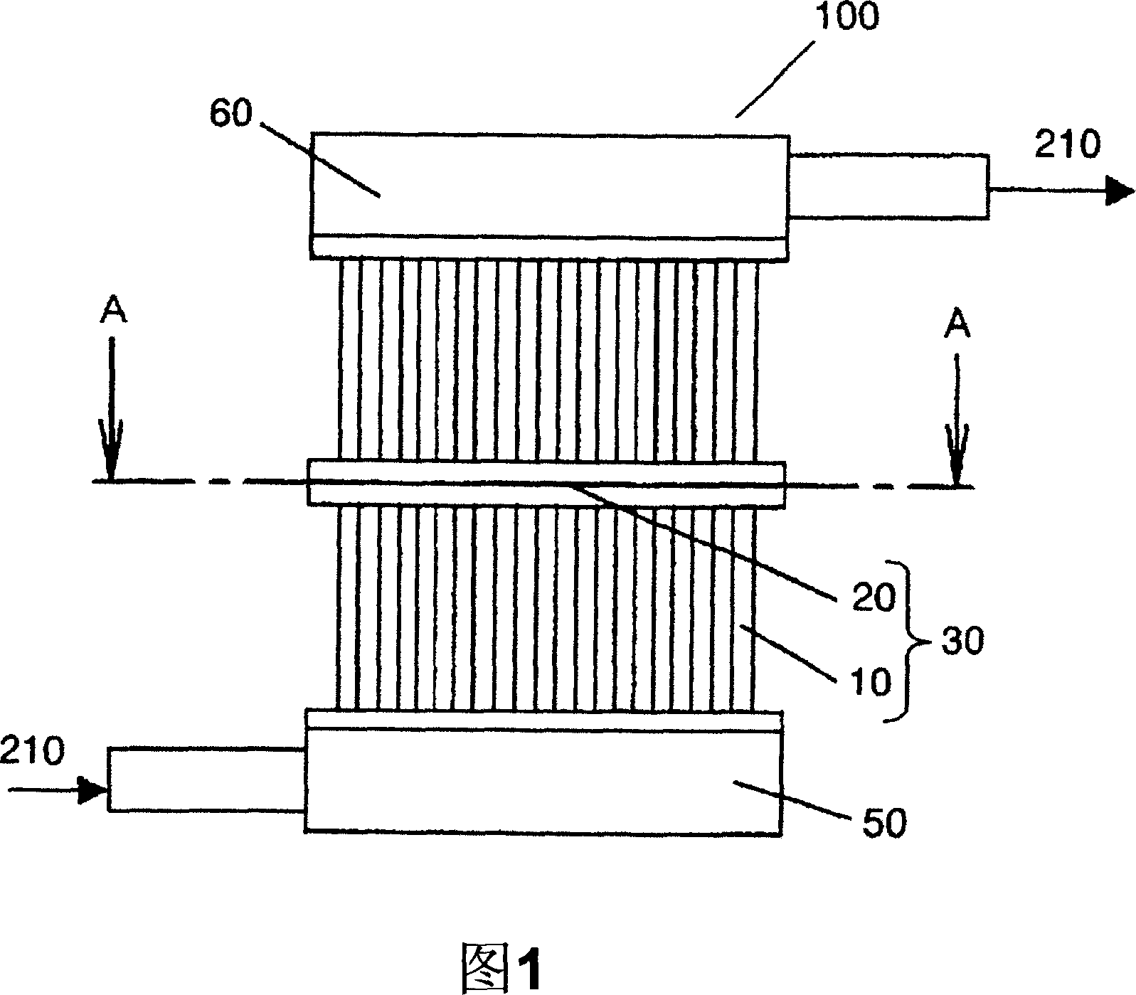
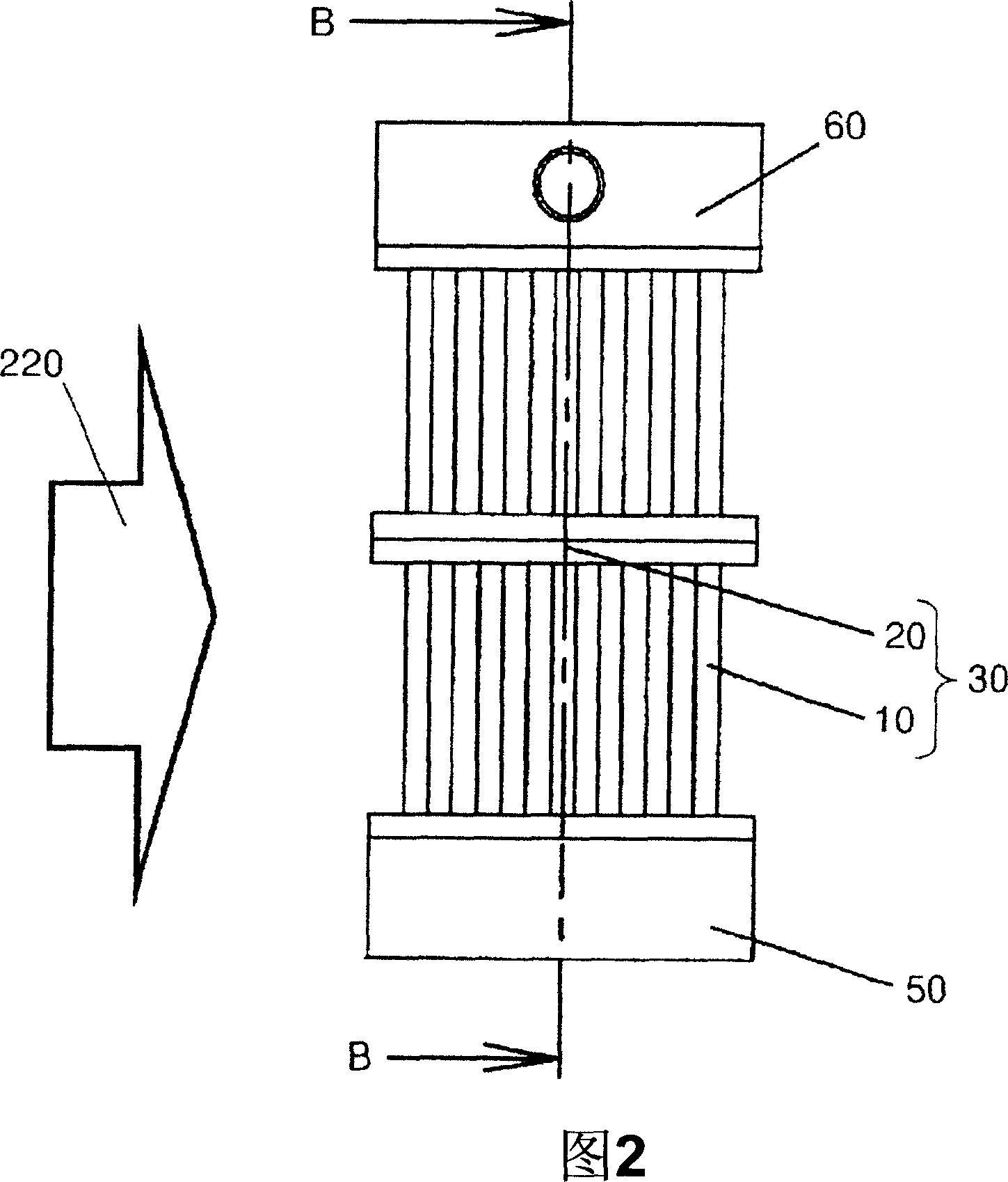
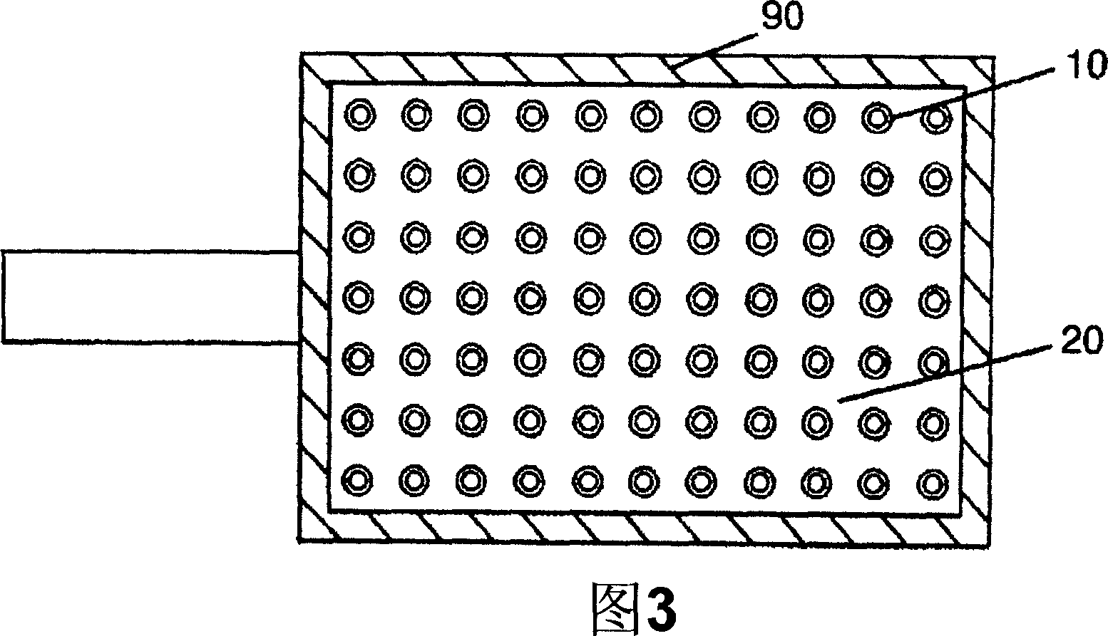
[0080] FIG. 1 is a front view of a heat exchanger according to Embodiment 1 of the present invention, and FIG. 2 is a side view. Fig. 3 is a sectional view of line A-A in Fig. 1, and Fig. 4 is a sectional view of line B-B in Fig. 2 .
[0081] As shown in FIGS. 1 to 4 , the heat exchanger 100 according to Embodiment 1 has a tube group block 30 composed of tubes 10 and substrates 20 . Furthermore, the two-layer tube group blocks 30 are connected by joining each other on the periphery 90 of the base plate 20 along the tube axis of the tube 10, and the inlet cover 50 and the outlet cover 60 are provided at both ends in the vertical direction.
[0082] In this embodiment, the tube 10 is a round tube and is provided with an internal fluid flow path. Furthermore, the shape of the pipe 10 may not be a round pipe. For example, it may be a tube having a rectangular cross-sectional shape, a polygonal tube, or an elliptical tube. In addition, the peripheries 90 of the substrate 20 are directly bonded to each other without using solder or an adhesive. Examples of such bonding methods include welding bonding, ultrasonic bonding, diffusion bonding, and the like. Therefore, by directly bonding the periphery 90 of the substrate 20 , it is possible to prevent the solder or the adhesive from melting out and clogging the inside of the tube 10 .
[0083] Diffusion bonding is used in this embodiment. Diffusion bonding is a method in which atomic diffusion (interdiffusion) occurs by simultaneously applying temperature and pressure to the extent that the base material does not melt, and bonding is performed using atomic bonding. Therefore, the base material will not melt out and the tube will not be damaged. 10 within blockage. In this way, by performing bonding by diffusion bonding without using brazing filler metal, not only can the generation of defective products such as brazing filler metal clogging the inside of the tube 10 be suppressed as much as possible, but also the heat exchanger 100 can be provided at a low price.
[0084] 5 to 7 are schematic diagrams illustrating the tube group block 30 of the heat exchanger 100 . FIG. 5 is a perspective view of the tube group block 30 , FIG. 6 is a front view thereof, and FIG. 7 is a top view thereof.
[0085] In the tube group block 30 , the tube 10 and the base plate 20 are integrally formed by injection molding or the like. It is preferable to use an inexpensive and easy-to-form resin material as the material for manufacturing the tube group block 30 . Since the pipe 10 has a small diameter and a large number, the shape of the pipe group block 30 is complicated. Therefore, when manufacturing by injection molding, it is preferable to use molding processing from the viewpoint of supplying the resin to the end. Resin material with low viscosity and good fluidity. By using such a resin material, not only can the number of defective products be reduced, but also the heat exchanger 100 can be provided at a low price.
[0086] In addition, when water or antifreeze is used as the internal fluid, if a resin material with a small water vapor transmission rate is used, the internal fluid is difficult to permeate. Therefore, not only the wall thickness of the tube 10 can be reduced, material costs can be reduced, but The heat exchanger 100 is provided at a low price.
[0087] As the resin material, it is preferable to use polypropylene (PP) or polyethylene terephthalate (PET), which has good fluidity, low water vapor transmission rate, and is inexpensive.
[0088] (Table 1)
[0089]
[0090] As shown in Table 1, PP or PET has a higher melt-flow rate (melt-flow rate) indicating viscosity and better fluidity than ABS. Therefore, the fillability to the mold during molding is good. In addition, PP or PET has a low water vapor transmission rate, so it can be formed thinner than ABS.
[0091] In addition, in this Embodiment 1, although the arrangement|positioning of the pipe|tube 10 is a checkerboard shape, it may be zigzag shape.
[0092] The operation and function of the heat exchanger 100 configured as described above will be described.
[0093] The internal fluid 210 flows into the inlet cover 50 , is divided by the tubes 10 , passes through the tube group block 30 , and flows out of the heat exchanger 100 from the outlet cover 60 . Outside the tube 10 , the external fluid 220 flows between the tubes 10 , and the internal fluid 210 and the external fluid 220 exchange heat through the tube 10 .
[0094] In addition, in this embodiment, two layers of tube group blocks 30 are laminated, but two or more layers may be laminated.
[0095] As described above, in the first embodiment, since the connecting tube group blocks 30 are formed in predetermined dimensions, the length of the tubes 10 of the tube group blocks 30 can also be shortened. The substrate 20 and the tube 10 can be simultaneously and easily manufactured by injection molding, die casting, or the like. Since there is no step of inserting and fixing the tube 10, the heat exchanger 100 can be provided at low cost.
[0096] In addition, in the first embodiment, they are bonded to each other on the periphery 90 of the substrate 20 . When connecting the tube group blocks 30, since the periphery 90 which is easy to handle from the outside is joined, the reliability of the joining is improved, and the number of man-hours is reduced, so that the heat exchanger 100 can be provided at a low price.
[0097] In addition, in Embodiment 1, since the tube group block 30 is manufactured using an inexpensive resin material, the heat exchanger 100 can be provided at low cost.
[0098] In addition, in the first embodiment, the peripheral edges 90 of the substrates 20 can be directly bonded to each other by diffusion bonding. Diffusion bonding does not require the use of solder or adhesive, and bonding can be achieved without melting the base material. As a result, the flow path in the tube 10 is not blocked, defective products can be greatly reduced, and the heat exchanger 100 can be provided at a low price.
Example Embodiment
[0099] (Embodiment 2)
[0100] Fig. 8 is a front view of a heat exchanger according to Embodiment 2 of the present invention, and Fig. 9 is a side view thereof. FIG. 10 is a sectional view along line C-C in FIG. 8 , and FIG. 11 is a sectional view along line D-D in FIG. 9 .
[0101] In FIGS. 8 to 11 , the heat exchanger 200 has a tube group block 130 composed of tubes 110 and a base plate 120 . Furthermore, the two-layer tube group blocks 130 are connected by jointing on the periphery 190 of the substrate 120 along the tube axis direction of the tube 110, and the inlet cover 150 and the outlet cover 160 are provided at both ends in the vertical direction.
[0102] In Embodiment 2, the cross-sectional shape of the tube 110 is flat, and the plurality of channels 115 are arranged along the longitudinal direction. The plurality of tubes 110 are provided on the substrate 120 so that their longitudinal directions are parallel to each other and at a predetermined interval therebetween. The peripheries 190 of the substrates 120 are directly bonded to each other without using solder or adhesive. Examples of such bonding methods include welding bonding, ultrasonic bonding, diffusion bonding, and the like. Then, by directly bonding the peripheries 190 of the substrates 120 to each other, it is possible to prevent the solder or the adhesive from melting out and clogging the inside of the tube 110 .
[0103] Diffusion bonding is used in this embodiment. Diffusion bonding is a method in which atomic diffusion (interdiffusion) phenomenon occurs by simultaneously applying temperature and pressure to the extent that the base material does not melt, and bonding is performed using atomic bonding. Therefore, the base material does not melt out and the tube 110 Internal blockage. In this manner, by joining by diffusion bonding without using brazing filler metal, not only can the generation of defective products that clog the inside of the tube 110 with brazing filler metal be greatly suppressed, but also the heat exchanger 200 can be provided at a low price.
[0104] 12 to 14 are schematic diagrams illustrating the pipe group block 130, FIG. 12 is a perspective view of the pipe group block according to Embodiment 2, FIG. 13 is a front view thereof, and FIG. 14 is a plan view thereof.
[0105] The tube group block 130 is integrally formed with the tube 110 and the substrate 120 by injection molding or the like. As a material for manufacturing the tube group block 130, it is preferable to use an inexpensive and easy-to-form resin material. By using such a resin material, not only can the number of defective products be reduced, but also the heat exchanger 200 can be provided at a low price.
[0106] In addition, when water or antifreeze is used as the internal fluid, if a resin material with a small water vapor transmission rate is used, the internal fluid is difficult to permeate. The heat exchanger 200 is provided at a low price.
[0107] As the resin material, it is preferable to use polypropylene (PP) or polyethylene terephthalate (PET), which has good fluidity and low water vapor transmission rate, and is inexpensive.
[0108] Next, the operation and function of the heat exchanger 200 configured as described above will be described.
[0109] The internal fluid 210 flows into the inlet cover 150 , is divided by the tubes 110 , passes through the tube group block 130 , and flows out of the heat exchanger 200 from the outlet cover 160 . Outside the tube 110 , since the external fluid 220 flows between the tubes 110 , the internal fluid 210 and the external fluid 220 exchange heat through the tube 110 .
[0110] In addition, in this embodiment, two layers of tube group blocks 130 are stacked, but it is not limited to two layers, and multiple layers of two or more layers may be stacked.
[0111] As described above, in the second embodiment, since the connecting pipe group blocks 130 are formed in predetermined dimensions, the length of the pipes 110 of the pipe group blocks 130 can also be shortened. The substrate 120 and the tube 110 can be easily and simultaneously produced by using methods such as injection molding or die casting. Since there is no process of inserting and fixing the tube 110, the heat exchanger 200 can be provided at a low price.
[0112] In addition, in the present embodiment, the peripheral edges 190 of the substrates 120 are bonded to each other. When connecting the tube group blocks 130, since the periphery 190 which is easy to handle from the outside is joined, the number of man-hours is reduced, the reliability of the joint is improved, and the heat exchanger 200 can be provided at a low price.
[0113] In addition, in Embodiment 2, the tube 110 is a porous tube provided with the multi-channel 115 inside the tube. By using the multi-hole tube, the number of tubes can be reduced without reducing the number of flow paths, so that the manufacture is easy, and the heat exchanger 200 can be provided at a low price.
[0114] In addition, in this embodiment, since the tube group block 130 is manufactured using an inexpensive resin material, the heat exchanger 200 can be provided at a low price.
[0115] In addition, in this embodiment, the peripheries 190 of the substrates 120 can be directly bonded to each other by diffusion bonding. Diffusion bonding does not require the use of solder or adhesive, and bonding can be achieved without melting the base material. As a result, the flow path 115 in the tube 110 is not blocked, defective products can be greatly reduced, and the heat exchanger 200 can be provided at a low price.
Example Embodiment
[0116] (Embodiment 3)
[0117] Fig. 15 is a front view of a heat exchanger according to Embodiment 3 of the present invention, and Fig. 16 is a side view thereof. FIG. 17 is a sectional view along line A-A in FIG. 16 , and FIG. 18 is a sectional view along line B-B in FIG. 16 . In addition, the same code|symbol is attached|subjected to the same element as Embodiment 1, and the description is simplified.
[0118] In FIGS. 15 to 18 , a heat exchanger 300 has a tube group block 40 composed of tubes 10 , base plates 20 and spacers 80 . Furthermore, the tube group block 40 is stacked in three layers along the flow direction of the internal fluid flowing in the tube 10, and the inlet cover 50 and the outlet cover 60 are provided at both ends in the vertical direction. Here, the spacer 80 is a portion protruding from the substrate in a stepwise manner at the periphery of the substrate 20 with a predetermined height and width.
[0119] In this embodiment, the tube 10 is a round tube and is provided with an internal fluid flow path. Furthermore, the shape of the tube 10 is not limited to a circular tube, and for example, a tube having a rectangular cross-sectional shape, a polygonal tube, or an elliptical tube may be used.
[0120] In the adjacent tube group blocks 40 , the spacers 80 provided on the peripheries of the substrates 20 are bonded to each other, and the mixing chamber 70 is formed between the bonded two substrates 20 . Furthermore, in Embodiment 3, the spacer 80 is provided on both adjacent tube group blocks 40 , but it is only necessary to provide the spacer 80 on at least one of the substrates. In this case, the spacer 80 of one of the tube group blocks 40 is bonded to the periphery of the substrate 20 of the other tube group block 40 . Here, the tube group blocks 40 are directly joined to each other without using brazing material. Since brazing filler metal is not used, clogging of the tube 10 by melting of the brazing filler metal does not occur.
[0121] In Embodiment 3, diffusion bonding is used for the above-mentioned bonding. Unlike brazing, diffusion bonding is a joining method in which the base material is heated to a temperature at which the base material does not melt while applying pressure. In diffusion bonding, atomic diffusion (interdiffusion) occurs, and bonding is performed by bonding of atoms. Therefore, the base material does not melt out and the inside of the tube 10 does not become clogged. In this way, by performing bonding by diffusion bonding without using brazing filler metal, not only can the occurrence of defective products that clog the inside of the tube 10 be greatly suppressed, but also the heat exchanger 300 can be provided at a low price.
[0122] In addition, the same effect can be obtained also by using the ultrasonic bonding method. As other direct bonding methods, welding bonding and pressure welding bonding can also be used.
[0123] 19 to 21 are diagrams illustrating the tube group block 40 . Fig. 19 is a perspective view of a tube group block of a heat exchanger 300 according to Embodiment 3, Fig. 6 is a front view thereof, and Fig. 7 is a plan view thereof.
[0124] The tube 10, the substrate 20, and the spacer 80 of the tube group block 40 are integrally formed by injection molding or the like. As a material for manufacturing the tube group block 40, an inexpensive and easy-to-form resin material is preferably used. Since the pipe 10 has a small diameter and a large number, and the shape of the pipe group block 40 is complicated, especially in the case of manufacturing by injection molding, from the viewpoint of supplying the resin to the end, it is preferable to use Resin material with low viscosity and good fluidity during molding. By using such a resin material, not only can the number of defective products be reduced, but also the heat exchanger 300 can be provided at a low price.
[0125] In addition, when water or antifreeze is used as the internal fluid, if a resin material with a small water vapor transmission rate is used, the internal fluid is difficult to permeate. And the heat exchanger 300 can be provided at a low price.
[0126] As the resin material, it is preferable to use polypropylene (PP) or polyethylene terephthalate (PET), which has good fluidity, low water vapor transmission rate, and is inexpensive.
[0127] Furthermore, in Embodiment 3, the arrangement shape of the tubes 10 is a checkerboard shape, but it may be a zigzag shape.
[0128] Next, the operation and function of the heat exchanger 300 configured as described above will be described. Furthermore, as shown in FIG. 15, the heat exchanger 300 is composed of three layers of tube group blocks 40a, 40b, and 40c.
[0129] The internal fluid 210 flows into the inlet cover 50, is divided by the tubes 10a, passes through the tube group block 40a, flows into the mixing chamber 70a, and is mixed. The mixed internal fluid 210 is divided by the tubes 10b again, passes through the tube group block 40b and the mixing chamber 70b, passes through the tube group block 40c, and flows out of the heat exchanger 300 from the outlet cover 60 . On the other hand, outside the tubes 10 ( 10 a , 10 b , 10 c ), since the external fluid 220 flows between the tubes 10 , the internal fluid 210 and the external fluid 220 exchange heat through the tubes 10 .
[0130] If a foreign matter or the like is mixed in to clog one of the tubes 10a, the internal fluid 210 does not flow in the tube 10a, and the tube 10a does not contribute to heat exchange. However, since in the tubes 10b, 10c located downstream of the tube 10a, the internal fluid 210 passing through other unblocked tubes 10a is mixed in the mixing chambers 70a, 70b, and then divided again, the internal fluid 210 can flow in the tube 10b. , Flow within 10c. As a result, the internal fluid 210 within the tubes 10b, 10c can contribute to heat exchange. Thus, by dividing the tube group block 40 along the flow direction of the internal fluid 210, even in the case of clogging, the area not contributing to heat exchange due to clogging can be reduced, and the amount of heat exchange can be prevented from significantly decreasing.
[0131] Also, when the amount of heat exchange is large, as shown in FIG. 16 , the temperature difference between the external fluid 220 and the internal fluid 210 flowing in the pipe 10d located upstream of the external fluid may become small. In this case, the internal fluid 210 flowing in the pipe 10d located on the upstream side of the external fluid and the internal fluid 210 flowing in the pipe 10e located on the downstream side of the external fluid are mixed in the mixing chambers 70a, 70b, and the flow in the pipe 10d The temperature difference between the internal fluid 210 and the external fluid becomes small due to the large heat exchange amount, and the internal fluid 210 flowing in the tube 10e maintains a large temperature difference with the external fluid 220 due to the small heat exchange amount. Therefore, the average temperature difference between the external fluid 220 and the internal fluid 210 becomes larger when passing through the tube group blocks 40b, 40c located downstream of the internal fluid, so that a large amount of heat exchange can be realized.
[0132] In addition, in this embodiment, three layers of tube group blocks 40 are stacked, but any multi-layer stacking may be sufficient as long as two or more layers are stacked.
PUM


Description & Claims & Application Information
We can also present the details of the Description, Claims and Application information to help users get a comprehensive understanding of the technical details of the patent, such as background art, summary of invention, brief description of drawings, description of embodiments, and other original content. On the other hand, users can also determine the specific scope of protection of the technology through the list of claims; as well as understand the changes in the life cycle of the technology with the presentation of the patent timeline. Login to view more.
Similar technology patents
Method for preparing bio-oil and/or pyrolytic gas by pyrolysis of biomass
Owner:ENN SCI & TECH DEV
Wavelength division multiplexing-passive optical network capable of integrating broadcast and communication services
Owner:SAMSUNG ELECTRONICS CO LTD
Preparation method for antibacterial nano-silver composite nanofiber mat by electrostatic spinning
Owner:DONGHUA UNIV
Three-dimensional printing device, three-dimensional printing system and three-dimensional printing method
Owner:CASIO COMPUTER CO LTD
Preparation method of mizue brocade straw activated charcoal
Owner:SHANDONG UNIV
Classification and recommendation of technical efficacy words
- low price
Asphalt-base carbon fiber prepared by coal directly liquefied residues and preparation method thereof
Owner:CHNA ENERGY INVESTMENT CORP LTD +1
Anode material for lithium-ion battery and preparation method of anode material
Owner:SOUTH CHINA UNIV OF TECH