Drip-irrigation water-current mud-sand separation system

A technology of water flow sediment and separation system, which is applied in the direction of filtration separation, separation method, and sediment separation by centrifugal force, etc. It can solve the problems that drip tanks cannot be used, and the efficiency and effect of sediment separation cannot be achieved, so as to achieve long service life, Separation effect stable effect

Inactive Publication Date: 2007-11-14
LANZHOU UNIVERSITY OF TECHNOLOGY +1
View PDF1 Cites 5 Cited by
  • Summary
  • Abstract
  • Description
  • Claims
  • Application Information

AI Technical Summary

Problems solved by technology

For the water flow with large sediment content and small sediment particle size, the separation of sediment by this technology cannot achieve good efficiency and effect, and the treated flowing water containing fine sediment cannot be used in drip tanks

Method used


Image

  • Drip-irrigation water-current mud-sand separation system
  • Drip-irrigation water-current mud-sand separation system

Examples


Embodiment Construction

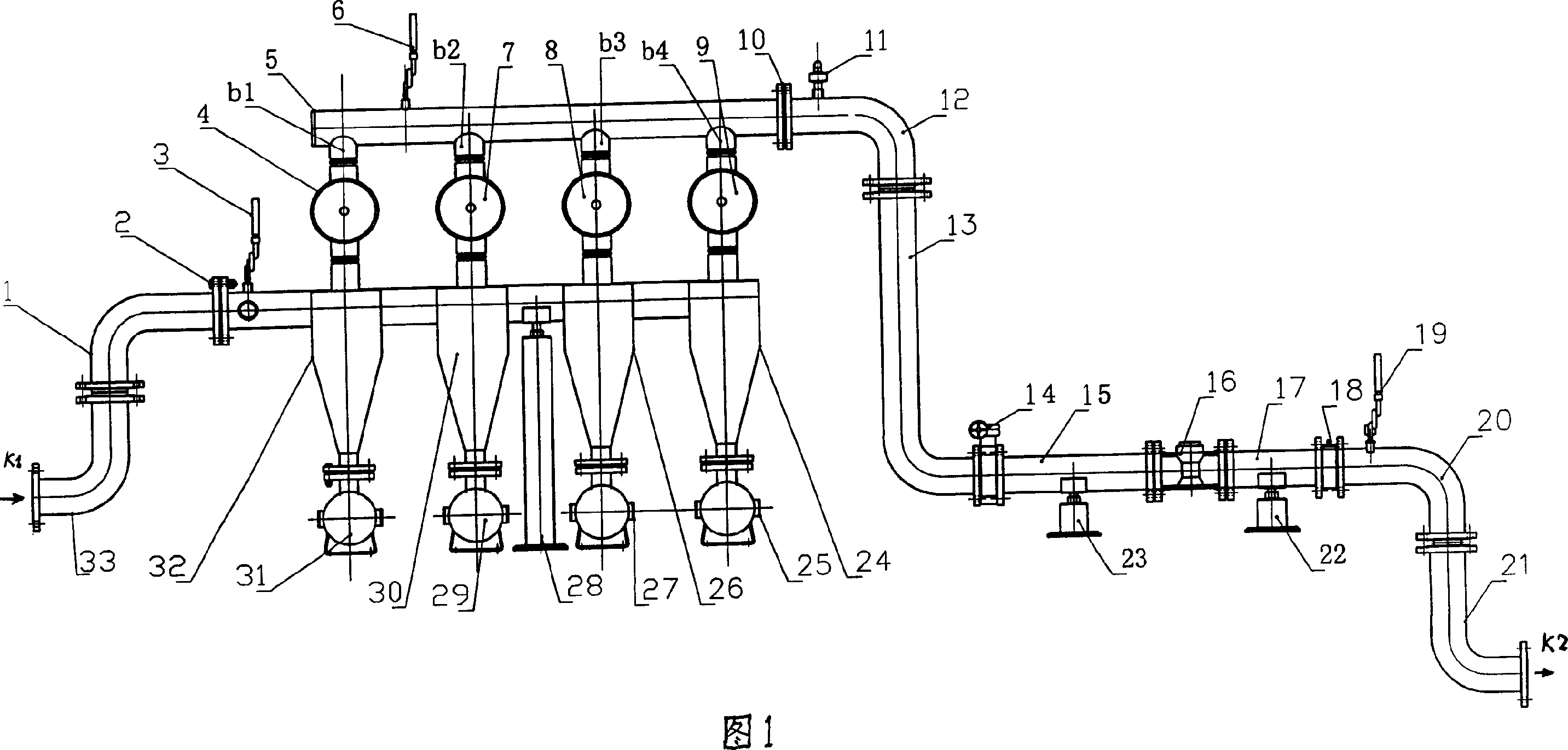
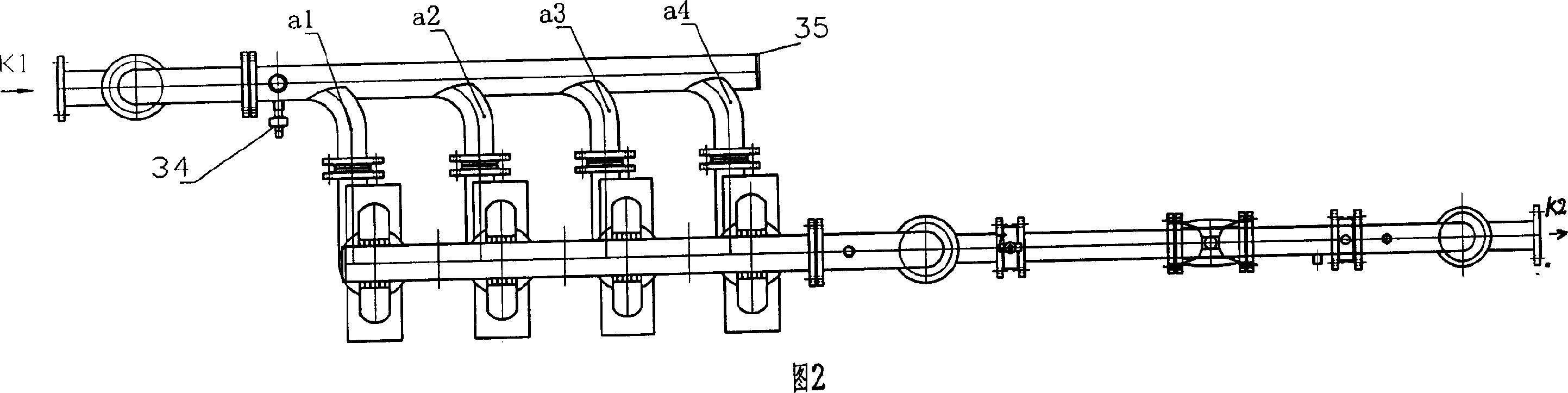
[0008] As shown in Figure 1 and Figure 2, it is a water flow sediment separation system for drip irrigation. The upper part of the cyclone centrifugal separator is a cylinder, and the lower part is a cone cylinder. The sediment outlet at the lower part of the cyclone centrifugal separator is connected to a sand collector. tank, the water inlet pipe is connected with the water distribution pipe 35, and the first distribution pipe a1, the second distribution pipe a2, the third distribution pipe a3, and the fourth distribution pipe a4 of four decomposed water volumes are respectively installed on the water distribution pipe 35. The water inlets of the pipes are installed obliquely on the water distribution pipe 35 relative to the water inlet flow direction respectively, and the cross-sectional area of ​​the water inlet of the first water distribution pipe a1 closest to the water inlet pipe is 1 / 4 of the cross-sectional area of ​​the water distribution pipe 35, and the second The c...


PUM


Abstract

The present invention relates to a dip irrigation water flow sediment separation system. Said system mainly includes the following several portions: water inlet pipe, several water-dividing pipes, several flow-dividing pipes, cyclone centrifugal separators, sand-collecting tank, sediment outlet, filters, flow-collecting pipe, water outlet pipe and dip irrigation system. Besides, said invention also provides the concrete operation method of said system.

Description

technical field [0001] The invention relates to devices for the application of free-swirling flow and filtration of water streams, also as pre-separation devices for watering gardens, fields, sports fields, etc. Background technique [0002] The background technology of the present invention is the Chinese utility model patent that application number is 96204592.6, and the name is called "a kind of mud-sand separator", and it has water inlet pipe, water outlet pipe, cylindrical shell, conical shell, sand joint, sand collection tank, The sand discharge port, the circumference of the cylindrical shell is tangentially connected to the water inlet pipe, the top of the cylindrical shell is vertically connected to the outlet pipe extending into the cylindrical shell, the cylindrical shell is connected to the conical shell, and the sand port at the lower part of the conical shell The sand collection tank is connected with a sand discharge port on the sand collection tank. For the ...

Claims


Application Information

Patent Timeline
Patent Type & Authority Applications(China)
IPC IPC(8): B01D36/04B01D21/26B04C5/28
Inventor 张力张杰武刘玉华赵学
Owner LANZHOU UNIVERSITY OF TECHNOLOGY
Why Eureka
Try Eureka