Sand-paving machine simultaneously having sieving sand pressure-reducing sand-guide functions

Inactive Publication Date: 2007-11-14
李明
View PDF0 Cites 5 Cited by
  • Summary
  • Abstract
  • Description
  • Claims
  • Application Information

AI Technical Summary

Problems solved by technology

This correspondingly requires frequent addition of sand to the sandbox during the operation, setting up a special site, and performing pre-screening operations with the help of special facilities, which not only affects the overall operating efficiency, but also requires time-consuming, laborious, and expensive sand screening tasks. , which is both troublesome and high in investment cost, so it is not ideal from the perspective of economy and practicality

Method used


Image

  • Sand-paving machine simultaneously having sieving sand pressure-reducing sand-guide functions
  • Sand-paving machine simultaneously having sieving sand pressure-reducing sand-guide functions

Examples


Embodiment 1

[0022] Embodiment 1 common type

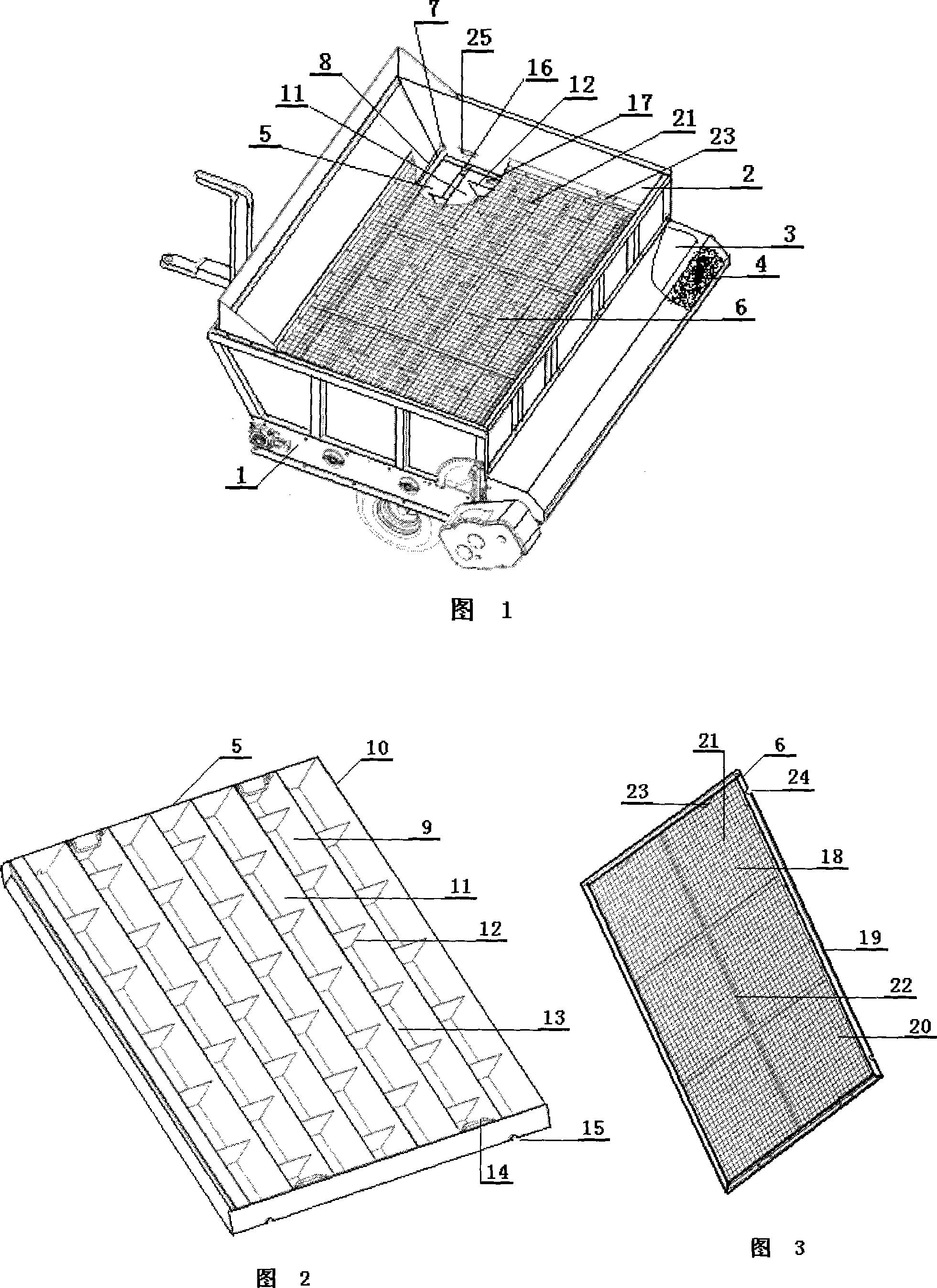
[0023] In Fig. 1, Fig. 2 and Fig. 3, the main body of the topdressing machine with the functions of sand screening and decompression and sand guiding of the present invention is composed of a frame 1, a sandbox 2 that takes out the sand mouth, a conveyor belt 3 driven by power and Composed of roller brushes 4, the conveyor belt 3 passes through and is arranged on the bottom of the sandbox 2, and the roller brushes 4 are arranged closely below the sand outlet. Pressure sand guide grid plate 5 and a sand screening grid plate 6 composed of the middle main surface 16 and the surrounding frame 17, wherein: the decompression sand guide grid plate 5 is horizontally arranged near the bottom of the box 2 above the conveyor belt 3 In terms of position, the middle main board 7 is connected by a number of small grids 11 composed of front and rear unidirectional inclined sides 9 and reinforcing ribs 10 arranged between the front and rear unidirectional inc...

Embodiment 2

[0025] Embodiment 2 vibration type

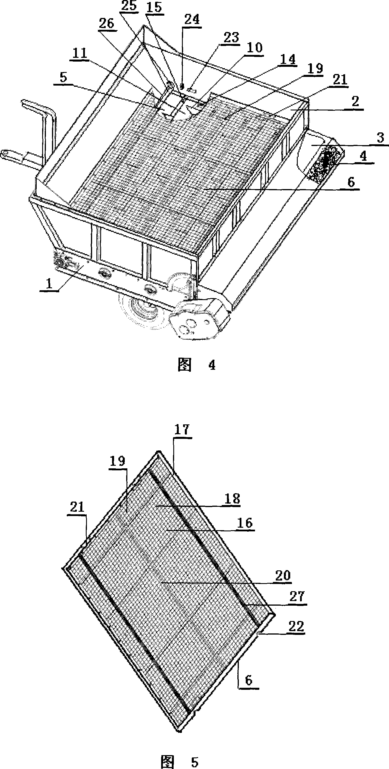
[0026]In Fig. 4 and Fig. 5, the main body of the sand topdressing machine with the functions of sand screening and decompression and sand guiding of the present invention is composed of a frame 1, a sand box 2 that is brought out of the sand mouth, a powered conveyor belt 3 and a roller brush 4 Composition, the conveyor belt 3 passes through and is set on the bottom of the sand box 2, and the roller brush 4 is placed close to the bottom of the sand outlet. It is characterized in that a decompression sand guide composed of a middle main board 7 and a surrounding frame 8 is arranged horizontally in the cavity of the sand box 2. Grid plate 5, a sand screening grid plate 6 made of the middle main surface 16 and the surrounding frame 17 and an upper band with a vibrating shaft 26 that drives the eccentric protrusion 25 of the sand screening grid plate 6 to vibrate, wherein: the The decompression and sand guide grid plate 5 is horizontally arrang...


PUM


Abstract

This invention involves a kind spread sand machine have both siftings leads the sand function and the reduced pressure, which is composed by the rack, the sandbox, the conveyer belt and rolls brushes. The conveyer belt passes through establishment in the sandbox base, rolls brushes clings establishes underneath the sand mouth, near the sandbox cavity bottom is equipped with the reduced pressure to lead the sand grid overlay, upside establised siftings the grid overlay and the belt eccentric tappet vibration revolution axis, the reduced pressure leads on the sand grid overlay to be equipped with the small grid which, the handle and the spacing concave buckle around certain belts the unidirectional inclined shape side and the stiffener constitute, siftings on the grid overlay to be equipped with by the belt specification mesh strainer, vertically and horizontally the overlapping stiffener, the handle and the spacing saw notch, in the sandbox cavityNear base and upside on the sidewall establishes separately has the spacing to hold the block. When work, the sand falls directly in siftings on the grid overlay, after sieving filters the whereabouts, the reduced pressure to lead the sand grid overlay leads the sand on the conveyer belt obtains with the sand, withstanding compared to carries less pressures than the sands quantity, it is advantageous in raises the overall working efficiency, the construction quality and the extension conveyer belt service life, has the very strong usability.

Description

technical field [0001] The invention relates to the technical field of agricultural and forestry machinery and equipment, in particular to a topdressing machine suitable for use in golf courses, football fields, lawn production bases, etc., which has the functions of sand screening and decompression and sand guiding. Background technique [0002] Sand topdressing machine is a mechanized operating device with sand-carrying and sand-dressing functions specially used for maintenance and maintenance of sports grounds and lawns. Currently, various types of sand topdressing machines on the market are mainly produced in the United States, Japan, the Netherlands and China. They are all composed of a frame, a sand box with a sand outlet, a power-driven conveyor belt and a roller brush. The roller brush is placed close to the bottom of the sand outlet, the conveyor belt is set on the bottom of the sand box, and the sand is directly loaded on the roller brush. It is set close to the bo...

Claims


Application Information

Patent Timeline
Patent Type & Authority Applications(China)
IPC IPC(8): E01C19/20
Inventor 李明
Owner 李明
Why Eureka
Try Eureka