Static-pressure supporting spherical self-aligning bearing seat

A self-aligning bearing and hydrostatic support technology, applied in the direction of bearing components, shafts and bearings, and rigid supports of bearing components, can solve the problems of large sliding friction resistance, insufficient lubrication, and unsatisfactory self-aligning effect, and achieve guaranteed Alignment effect, the effect of reducing sliding frictional resistance

Inactive Publication Date: 2007-11-14
UNIV OF SCI & TECH LIAONING
View PDF0 Cites 7 Cited by
  • Summary
  • Abstract
  • Description
  • Claims
  • Application Information

AI Technical Summary

Problems solved by technology

Due to insufficient lubrication, especially for large heavy-duty slewing equipment, the sliding friction resistance is relatively large, resulting in unsatisfactory centering effect

Method used


Image

  • Static-pressure supporting spherical self-aligning bearing seat
  • Static-pressure supporting spherical self-aligning bearing seat
  • Static-pressure supporting spherical self-aligning bearing seat

Examples


Embodiment 1

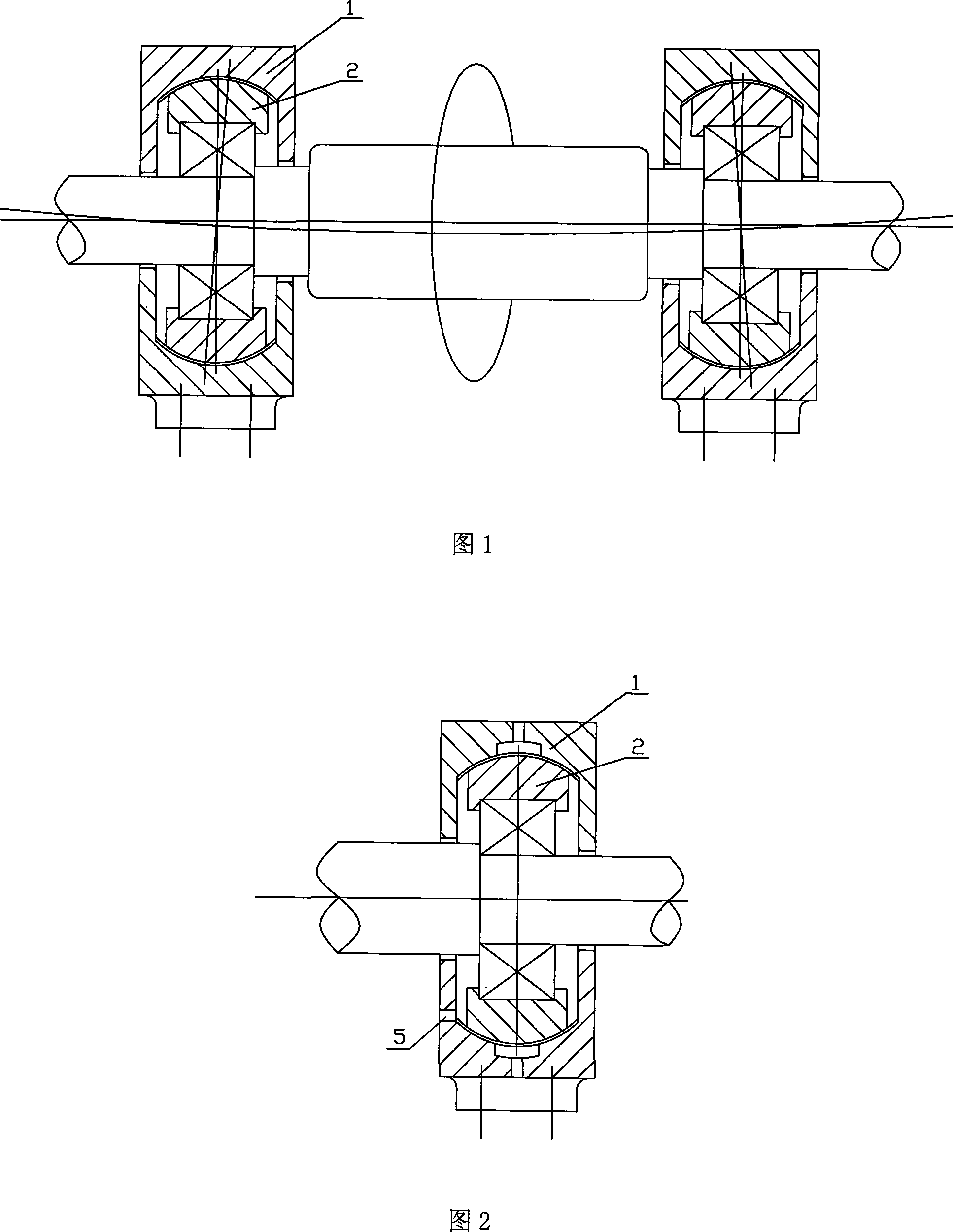
[0019] As shown in Figures 2 and 3, a spherical self-aligning bearing seat with static pressure support includes a fixed seat 1 and a moving body 2, and three oil chambers are arranged on the upper and lower concave spherical surfaces within the range of 180° of the fixed seat 1. 3. The oil chamber 3 is connected with the oil passage 4 connected to the external oil source, and the pressure oil is provided by the external oil source, forming a complete oil film between the fixed seat 1 and the moving body 2, and the bearing seats can be flexible when they work in groups Automatic centering. An oil return circuit 5 is arranged in the fixed seat, and the oil return circuit 5 is connected to the oil source through a pipeline connected thereto, so that the oil flowing out from the gap between the fixed seat and the moving body returns to the oil source through the oil return circuit.

[0020] The concave spherical surface of the seat 1 is a 360° annular spherical surface.

Embodiment 2

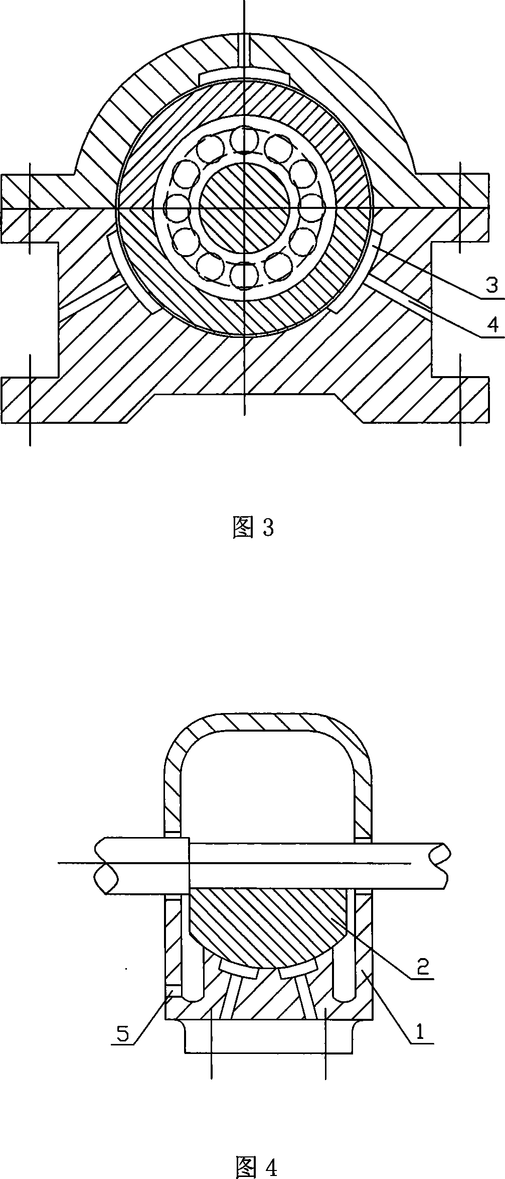
[0022] As shown in Figures 4 and 5, a spherical self-aligning bearing seat with static pressure support includes a fixed seat 1 and a moving body 2, and a plurality of oil chambers 3 are arranged on the concave spherical surface within 180° of the fixed seat 1. The cavity 3 is connected with an oil passage 4 connected to an external oil source, and the pressure oil is provided by the external oil source, forming a complete oil film between the fixed seat 1 and the moving body 2, and the flexible and automatic centering can be realized when the bearing seats work in groups . An oil return circuit 5 is arranged in the fixed seat, and the oil return circuit 5 is connected with the pipeline.

[0023] The concave spherical surface of the seat 1 is a partial annular spherical surface of 180°.

Embodiment 3

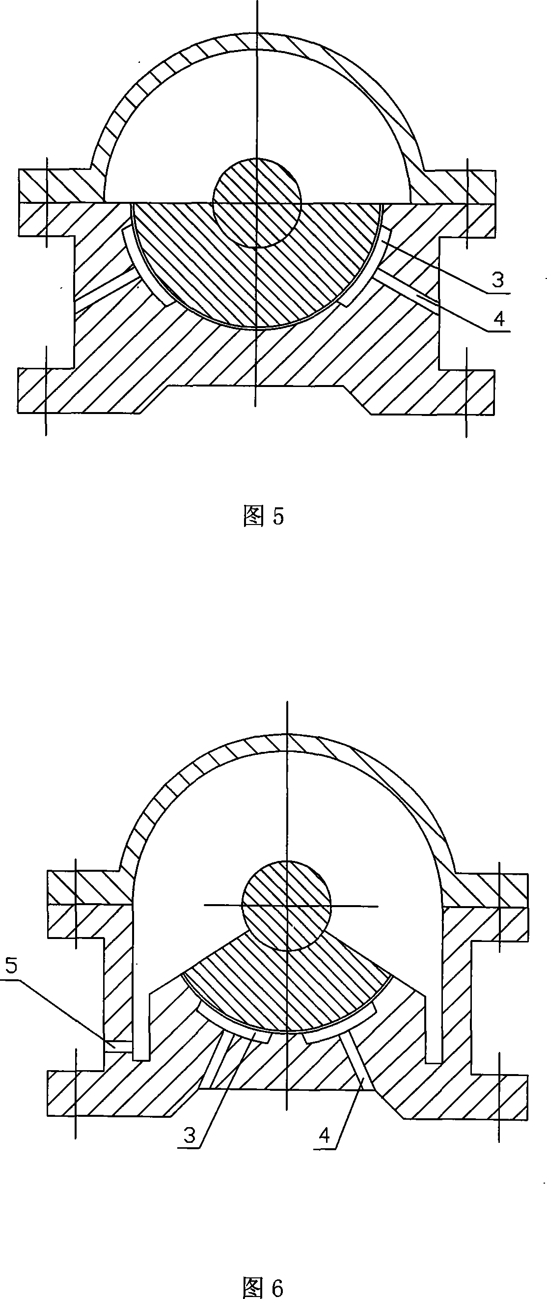
[0025] As shown in Figure 6, a spherical self-aligning bearing seat with static pressure support includes a fixed seat 1 and a moving body 2, and a plurality of oil chambers 3 are arranged on the concave spherical surface within the range of 180° less than the fixed seat 1. 3 is connected with an oil passage 4 connected to an external oil source, and the pressure oil is provided by the external oil source to form a complete oil film between the fixed seat 1 and the moving body 2, and the bearing seats can realize flexible and automatic centering when they work in groups. An oil return circuit 5 is arranged in the fixed seat, and the oil return circuit 5 is connected with the pipeline.

[0026] The concave spherical surface of the seat 1 is a partial annular spherical surface less than 180°.


PUM


Abstract

This invention relates to a rotary equipment housings, specifically is a hydrostatic bearing housings spherical aligning including fixed and dynamic blocks, the blocks in the concave spherical surface cavity with a number of oil, gas chamber connected with external oil source is connected Circuit. There is set to Block Oil, Oil and pipeline connected to. Block set concave spherical ring of 360 degree spherical, aspherical 180 degree partial ring and less than 180 degree partial annular spherical three types. Compared with the existing technology, the benefits of this invention lies: in the sphere aligning the two housings mutual coordination between the spherical form a complete oil film and realized the liquid lubrication, a decrease of sliding friction, thus ensuring that the spherical bearings Block aligning role.

Description

technical field [0001] The invention relates to a bearing seat used for rotary equipment, in particular to a static pressure supporting spherical surface self-aligning bearing seat. Background technique [0002] At present, among the bearing housings used in domestic rotary equipment, there is a type with self-centering function. The structure is a spherical self-aligning type, which is composed of a fixed seat and a moving body. The fixed seat is a concave spherical surface, and the moving body is a convex spherical surface with the same nominal size. The lubrication methods of the two mating surfaces are mostly grease lubrication or thin oil lubrication. Due to insufficient lubrication, especially for large and heavy-duty slewing equipment, the sliding friction resistance is relatively large, resulting in unsatisfactory centering effect. Contents of the invention [0003] In order to solve the above problems, the object of the present invention is to provide a method of...

Claims


Application Information

Patent Timeline
Patent Type & Authority Applications(China)
IPC IPC(8): F16C35/04
Inventor 吴晓元陈忠基
Owner UNIV OF SCI & TECH LIAONING
Why Eureka
Try Eureka