
Desk top liquid crystal display device

A liquid crystal display device and liquid crystal display technology, which are applied in optics, instruments, electrical digital data processing, etc., can solve the problems of inconvenient images on the liquid crystal display screen 11, users cannot see clearly, and general products have no structure.

Inactive Publication Date: 2007-11-14
GIGNO TECH CO LTD
View PDF0 Cites 1 Cited by
  • Summary
  • Abstract
  • Description
  • Claims
  • Application Information

AI Technical Summary

Problems solved by technology

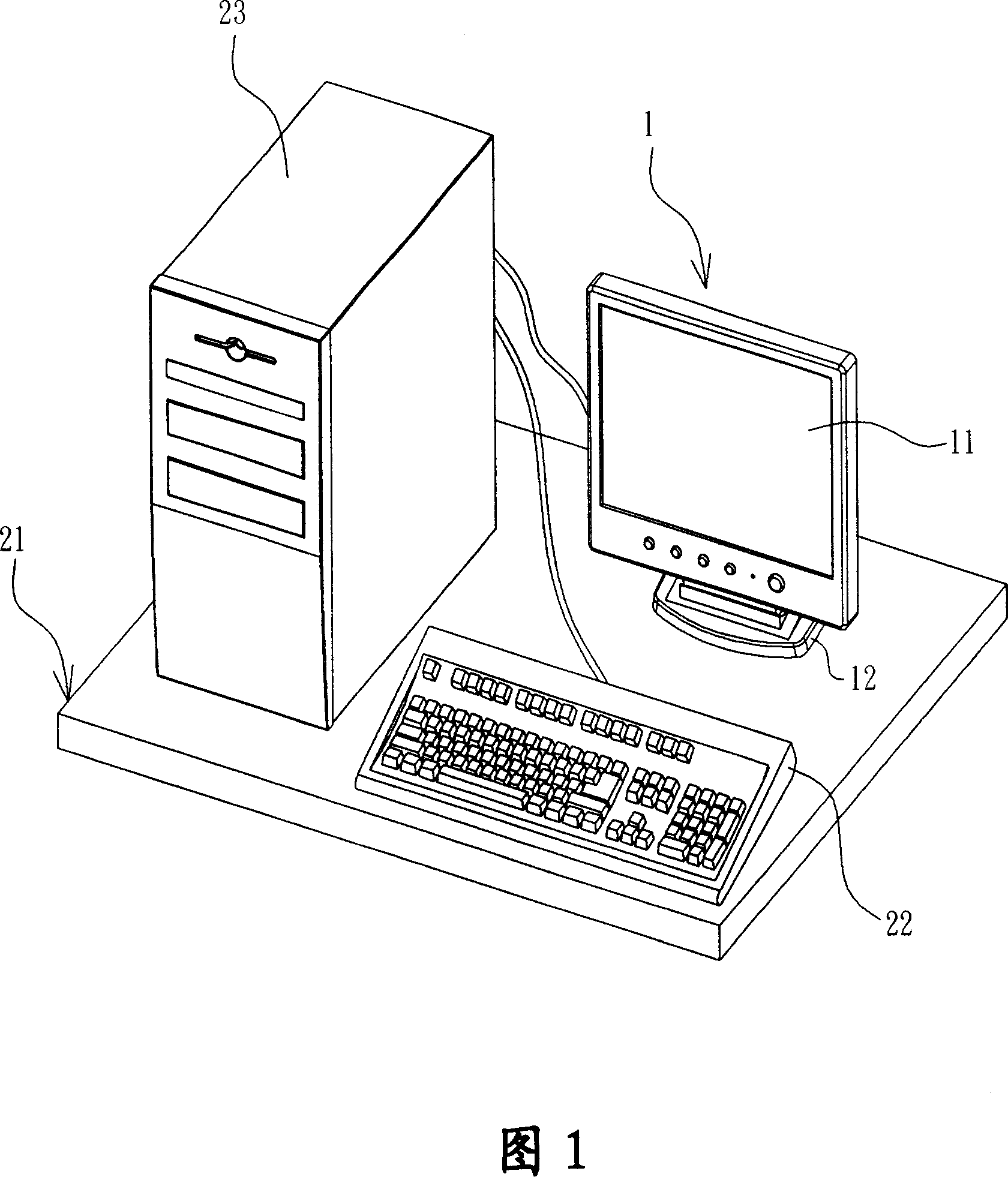
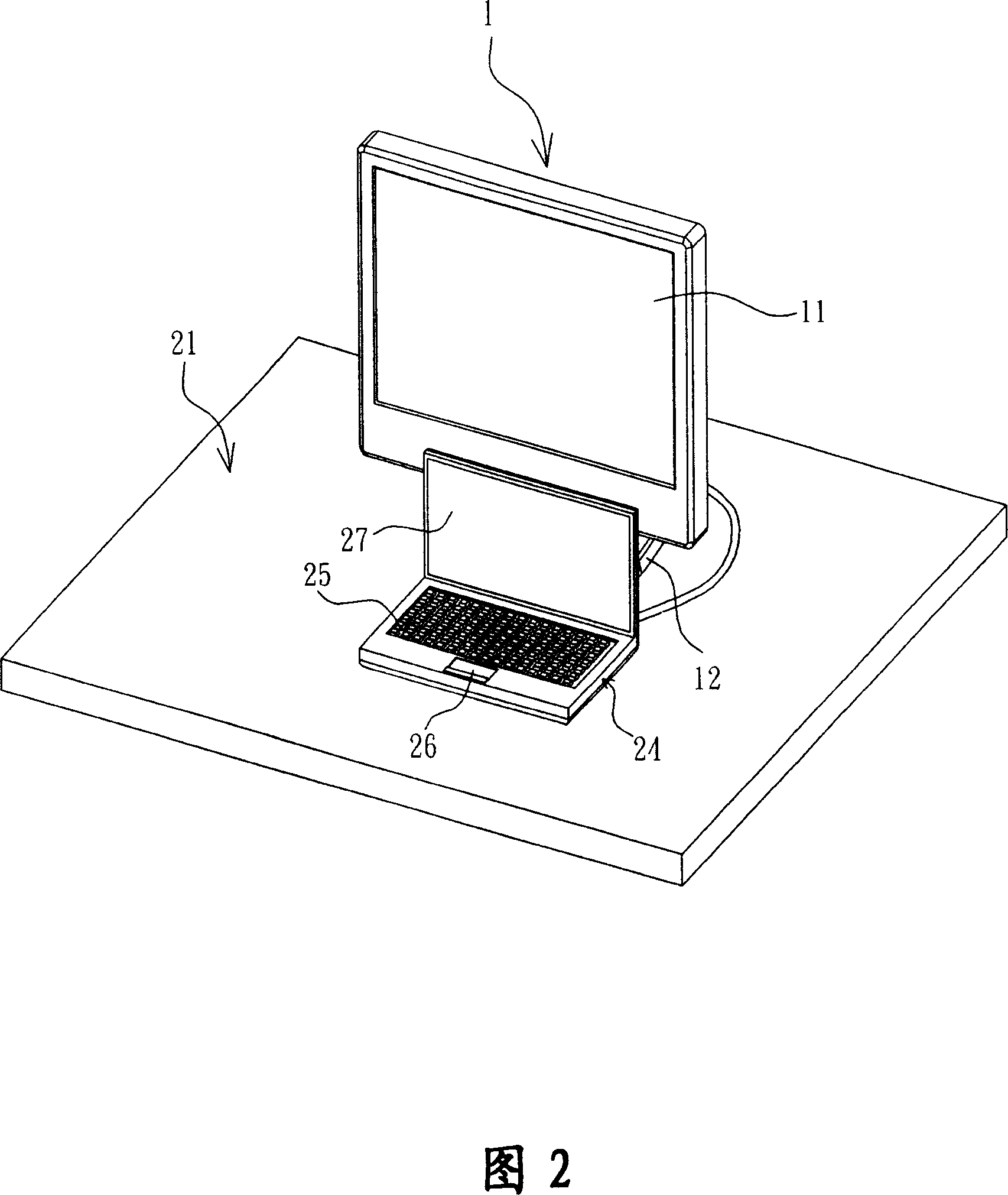
But in this case, the notebook computer 24 occupies more space on the desktop 21. If the desktop 21 is smaller, it will not be possible to combine the notebook computer 24 and the desktop liquid crystal display device 1 in this way, and because the keyboard 25 or the touch panel 26 is far from the desk. The top-type liquid crystal display device 1 is far away, so the user may not be able to see clearly the picture of the liquid crystal display screen 11 and is inconvenient to operate the notebook computer 24
[0007] This shows that above-mentioned existing desktop liquid crystal display device obviously still has inconvenience and defect in structure and use, and urgently needs to be further improved
In order to solve the above-mentioned problems, the relevant manufacturers have tried their best to find a solution, but no suitable design has been developed for a long time, and the general products do not have a suitable structure to solve the above-mentioned problems. This is obviously related. The problem that the industry is eager to solve

Method used


Image

  • Desk top liquid crystal display device
  • Desk top liquid crystal display device
  • Desk top liquid crystal display device

Examples


Embodiment Construction

[0056] In order to further explain the technical means and effects of the present invention to achieve the intended purpose of the invention, the specific implementation, structure, characteristics and details of the desktop liquid crystal display device proposed according to the present invention will be described below in conjunction with the accompanying drawings and preferred embodiments. Its effect is described in detail below.

[0057] The desktop liquid crystal display device according to the preferred embodiment of the present invention will be described below with reference to related drawings, wherein the same elements will be described with the same reference symbols.

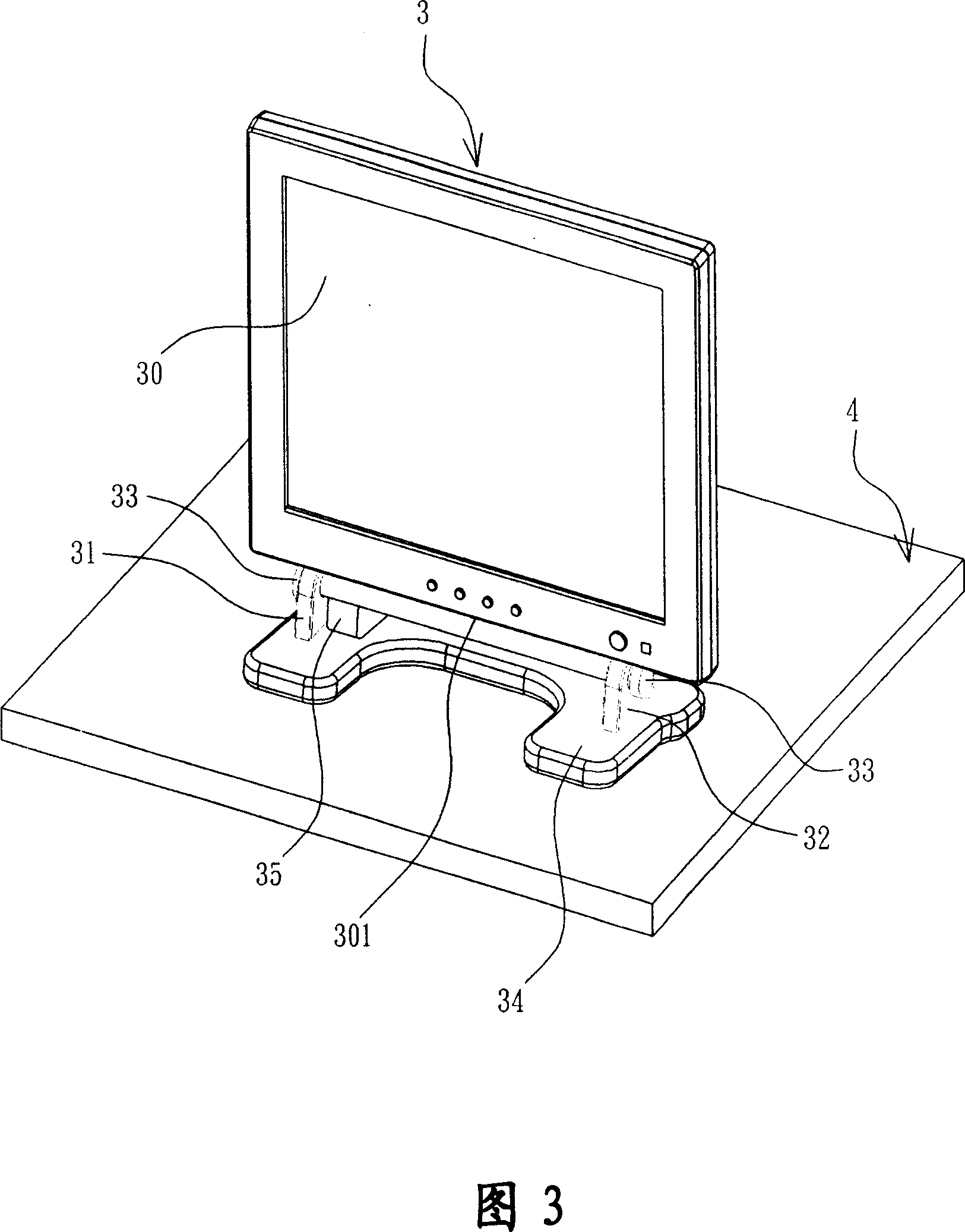
[0058] Please refer to FIG. 3 , which is a schematic diagram showing a desktop liquid crystal display device according to a preferred embodiment of the present invention. The desktop liquid crystal display device 3 according to the first preferred embodiment of the present invention is placed on a su...


PUM


Abstract

The invention is a LCD on a desktop is placed on a surface. Includes an LCD screen, first screen, first and a second stent, a liquid crystal display screen towards the end of the surface of a side The first stents and stent group in the second liquid crystal display screens, liquid crystal display screens and from the side towards the end of the exposed surface, and first and second stent is placed on the surface to support the LCD screen, The first stents and stent from the end of the second side from the exposed part of more than 25 cm. The present invention is reserved for the use of other electronic devices space, the first stent and stent exposed to the end of the second side of the more than 25 centimeters apart, another electronic device can be placed in the first and second stent between the stent, so that other electronic devices can not only with desktop LCD devices placed nearby, and the cover can be avoided its LCD screen, so that users more convenient to watch the LCD screen to operate the laptop computer, suitable for practical .

Description

technical field [0001] The present invention relates to a liquid crystal display device, in particular to a space reserved for another electronic device, so that the other electronic device can not only be placed adjacent to the desktop liquid crystal display device, but also can prevent it from covering the liquid crystal display screen desktop liquid crystal display device. Background technique [0002] With the vigorous development of the information industry, various types of electronic products have gradually become popular, and the new generation of products is becoming more and more sophisticated. Taking the display device of a computer (i.e., a computer) as an example, the traditional cathode ray tube display device has gradually become increasingly popular due to its large size. Eliminated by thin and light liquid crystal display devices. [0003] Please refer to FIG. 1 , which is a schematic diagram showing a conventional desktop liquid crystal display device used...

Claims


Application Information

Patent Timeline
Patent Type & Authority Applications(China)
IPC IPC(8): G02F1/1333G12B9/08G06F1/16
Inventor 林峰立
Owner GIGNO TECH CO LTD
Learn More