Ethernet relay device and method

A relay device, Ethernet technology, applied in the field of network communication, can solve the problem of high transmission distance cost, and achieve the effects of low cost, reliable regeneration and simple structure

Active Publication Date: 2011-08-17
NEW H3C TECH CO LTD
View PDF0 Cites 0 Cited by
  • Summary
  • Abstract
  • Description
  • Claims
  • Application Information

AI Technical Summary

Problems solved by technology

[0005] The purpose of the present invention is to provide an Ethernet relay device and a relay transmission method for Ethernet signals to solve the existing technical problem of using a two-port switch as a relay to extend the transmission distance and the high cost

Method used


Image

  • Ethernet relay device and method
  • Ethernet relay device and method
  • Ethernet relay device and method

Examples


Embodiment Construction

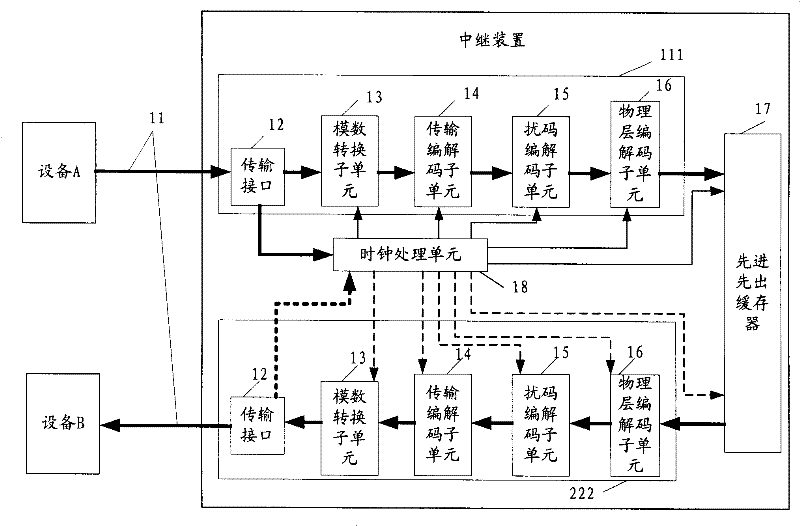
[0027] see figure 1 , which is a structural schematic diagram of the first embodiment of an Ethernet relay device disclosed in the present invention. In order to clarify the application environment of the device of the present invention, in figure 1 It also shows the peripherals connected to it. The relay device is arranged between network equipment A and network equipment B, and equipment A and equipment B perform data transmission through an electrical transmission medium 11 such as a network cable. The relay device includes first and second physical layer processing units 111 and 222 , a first-in first-out buffer 17 connected between the two physical layer processing units, and a clock processing unit 18 . The first physical layer processing unit 111 and the second physical layer processing unit 222 are coupled through a digital interface.

[0028] Wherein, the clock processing unit 18 is used to recover the receiving clock from the input signal and provide it to the fir...


PUM


Abstract

The relay device includes process units in first and second physical layers in use for carrying out process in physical layer for input signals. Through digital interfaces, process units in first and second physical layers are coupled. Since design of the process units in each physical layer is only under architecture of traditional PHY chip at most, thus structure of each part inside the relay device is simple. Under lower cost, the invention realizes purpose of signal relay.

Description

technical field [0001] The invention relates to the technical field of network communication, in particular to an Ethernet relay device and an Ethernet signal relay transmission method. Background technique [0002] For Ethernet transmission, the transmission distance is a problem that technicians are very concerned about. At present, the transmission distance using electrical transmission media such as network cables is generally limited to within 100 meters. If special coding at the physical layer or digital signal processing technology is used to pre-emphasize in the sending direction and equalize in the receiving direction, the transmission distance of electrical transmission can be extended to several hundred meters. The transmission distance using optical transmission media such as optical fibers can reach thousands of meters. But no matter which transmission method is adopted, technicians hope to be able to transmit farther on this basis. [0003] So there is a met...

Claims


Application Information

Patent Timeline
Patent Type & Authority Patents(China)
IPC IPC(8): H04B7/14H04W84/00
Inventor 于洋
Owner NEW H3C TECH CO LTD
Why Eureka
Try Eureka