AC motor drive system

A technology of AC motor and drive system, which is applied in the direction of AC motor control, DC motor deceleration device, motor generator control, etc. It can solve the problems of DC bus voltage drop and DC bus voltage rise, and achieve reliable power regeneration Effect

Inactive Publication Date: 2019-01-22
MITSUBISHI ELECTRIC CORP
View PDF7 Cites 0 Cited by
  • Summary
  • Abstract
  • Description
  • Claims
  • Application Information

AI Technical Summary

Problems solved by technology

According to the technology described in Patent Document 1, compared with the DC bus voltage value at no load when the AC motor performs neither power running operation nor regenerative operation, there is a clear difference in the following state, that is, in the AC motor The DC bus voltage value increases during regeneration, and the DC bus voltage value decreases during power operation of the AC motor

Method used


Image

  • AC motor drive system
  • AC motor drive system
  • AC motor drive system

Examples


Embodiment approach 1

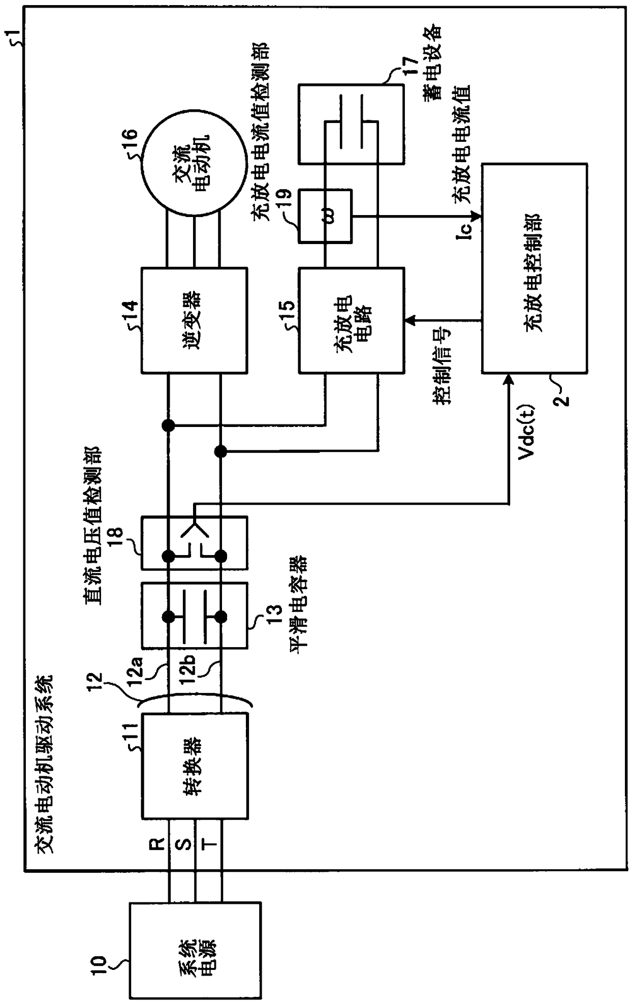
[0031] figure 1 It is a block diagram showing the overall configuration of Embodiment 1 of the AC motor drive system according to the present invention. figure 1 The illustrated AC motor drive system 1 includes a charge and discharge control unit 2, a converter 11, a DC bus 12, a smoothing capacitor 13, an inverter 14, a charge and discharge circuit 15, an AC motor 16, an electrical storage device 17, and a DC voltage value detection unit. part 18 and charge and discharge current value detection part 19. Towards figure 1The illustrated AC motor drive system 1 is supplied with AC power from a system power source 10 such as a power plant or a substation facility in a factory via wiring lines R, S, and T. Converter 11 converts AC power from system power supply 10 into DC power. The converted DC power is output from the converter 11 to the DC bus 12 . Furthermore, the DC bus 12 has a high potential side DC bus 12a and a low potential side DC bus 12b. The smoothing capacitor 1...

Embodiment approach 2

[0087] Figure 14 It is a block diagram showing the overall configuration of Embodiment 2 of the AC motor drive system according to the present invention. Figure 14 The illustrated AC motor drive system 1a includes a charge and discharge control unit 2a, a converter 11a, a DC bus 12, a smoothing capacitor 13, an inverter 14, a charge and discharge circuit 15, an AC motor 16, an electrical storage device 17, a DC voltage value detection part 18 and charge and discharge current value detection part 19. Converter 11a outputs regeneration period flag Fd to charge / discharge control unit 2a. The regeneration period flag Fd is a signal indicating that it is valid only while the converter 11 a is regenerating electric power from the DC bus 12 to the system power supply 10 . The regeneration period flag Fd is not valid when there is no load or when the converter 11a is supplying electric power from the system power supply 10 to the DC bus 12 . Figure 14 The AC motor drive system 1...

Embodiment approach 3

[0095] Figure 16 It is a block diagram showing the overall configuration of Embodiment 3 of the AC motor drive system according to the present invention. Figure 16 The shown AC motor drive system 1b includes a charge and discharge control unit 2b, an AC voltage value detection unit 8, a converter 11, a DC bus 12, a smoothing capacitor 13, an inverter 14, a charge and discharge circuit 15, an AC motor 16, a power storage Device 17 , DC voltage value detection unit 18 and charge and discharge current value detection unit 19 . Figure 16 The AC motor drive system 1b of the present embodiment shown and figure 1 The AC motor drive system 1 of Embodiment 1 shown differs in the presence of the AC voltage value detection unit 8 and the charge / discharge control unit 2 b which inputs the AC voltage value Vac which is the output of the AC voltage value detection unit 8 . The AC voltage value detection unit 8 is connected to the system power supply 10 side of the converter 11, detects...


PUM


Abstract

In order to obtain an AC motor drive motor system in which the converter (11) reliably regenerates electric power to the system power supply (10), there is a method based on the DC voltage value on the output side of the converter (11) and the charging and discharging of the power storage device (17). The charging and discharging control unit (2) controls the charging and discharging circuit (15) according to the current value. The electric storage device (17) is charged with DC power from the DC bus (12) and discharged to the DC bus (12). The control unit (2) charges the power storage device (17) so that the DC voltage value becomes the The voltage threshold corresponding to the power threshold, in the case that the regenerative power is less than or equal to the power threshold, if the DC voltage value reaches greater than or equal to the regeneration start voltage threshold, the converter (11) performs a regeneration action, and if the regenerative power is less than or equal to the regeneration end voltage threshold, the converter (11) ends the regenerative operation, and the time average value of the DC voltage value during the regenerative operation is lower than the no-load condition when the converter (11) does not perform power supply and regeneration.

Description

technical field [0001] The invention relates to an AC motor driving system. Background technique [0002] At present, as an example of the configuration of an AC motor drive system, an AC motor drive system in which an inverter and a charging / discharging circuit are connected via a smoothing capacitor to convert AC power from a system power supply is given. The output side of the DC power converter, that is, the DC bus, is connected in parallel. The inverter converts the DC power into AC power with a voltage value and frequency different from that of the system power supply in order to drive the AC motor. The charging and discharging circuit is used for storage. , Release DC power storage equipment for charging and discharging. [0003] For example, Patent Document 1 discloses a technique of charging a part of the regenerative power to the power storage device based on the voltage value of the DC bus line raised by the regenerative power from the AC motor to regenerate the ...

Claims


Application Information

Patent Timeline
Patent Type & Authority Patents(China)
IPC IPC(8): H02P27/06
CPCH02P3/18H02J7/14H02J7/345H02P27/06H02P3/14
Inventor 渡部一喜田渊朗子神田善则
Owner MITSUBISHI ELECTRIC CORP
Why Eureka
Try Eureka