
Non-positive fit elastic rail connection device for track systems

A technology of fixing devices and elastic rails, applied in the direction of rails, fixed rails, roads, etc., can solve the problem of increasing bolt load and achieve the effect of small structural space

Inactive Publication Date: 2011-01-26
SCHWIHAG
View PDF2 Cites 0 Cited by
  • Summary
  • Abstract
  • Description
  • Claims
  • Application Information

AI Technical Summary

Problems solved by technology

The clamping force of the clamping element acts additionally on the prestressing force of the sleeper bolts, thereby additionally increasing the load on the bolts
Furthermore, the mounting of the clamping elements can only be achieved by means of sleeper bolts or locking bolts

Method used


Image

  • Non-positive fit elastic rail connection device for track systems
  • Non-positive fit elastic rail connection device for track systems
  • Non-positive fit elastic rail connection device for track systems

Examples


Embodiment Construction

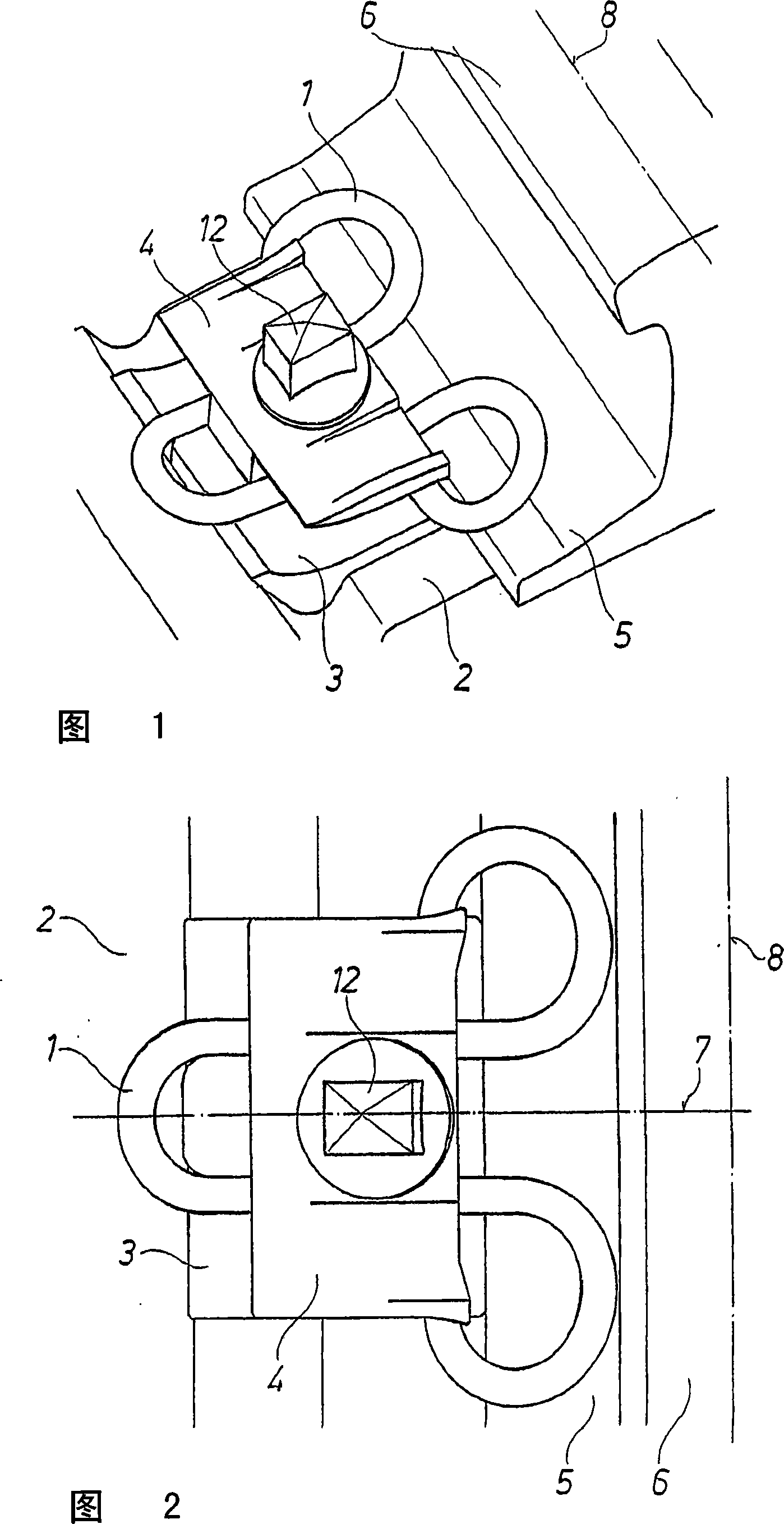
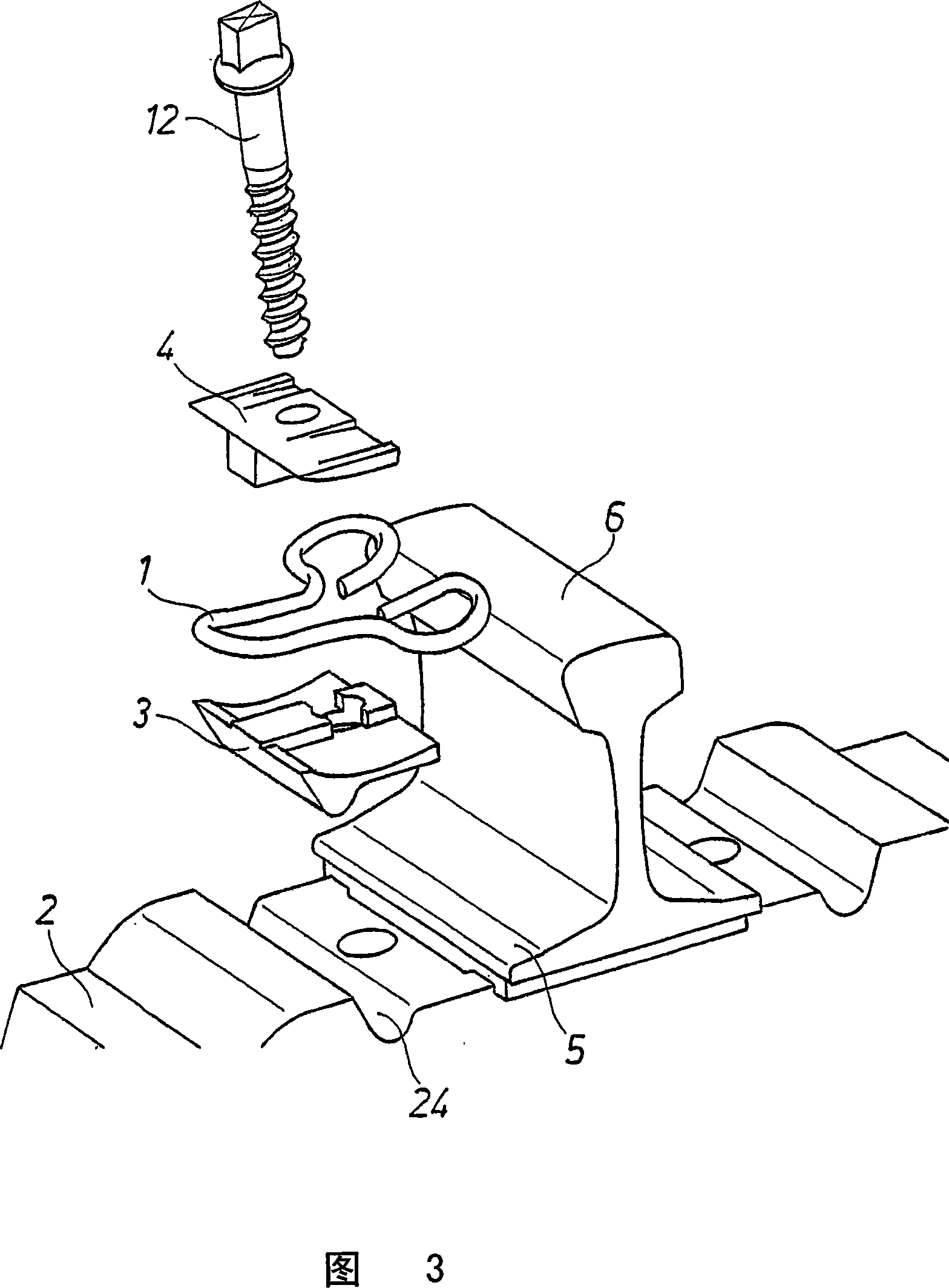
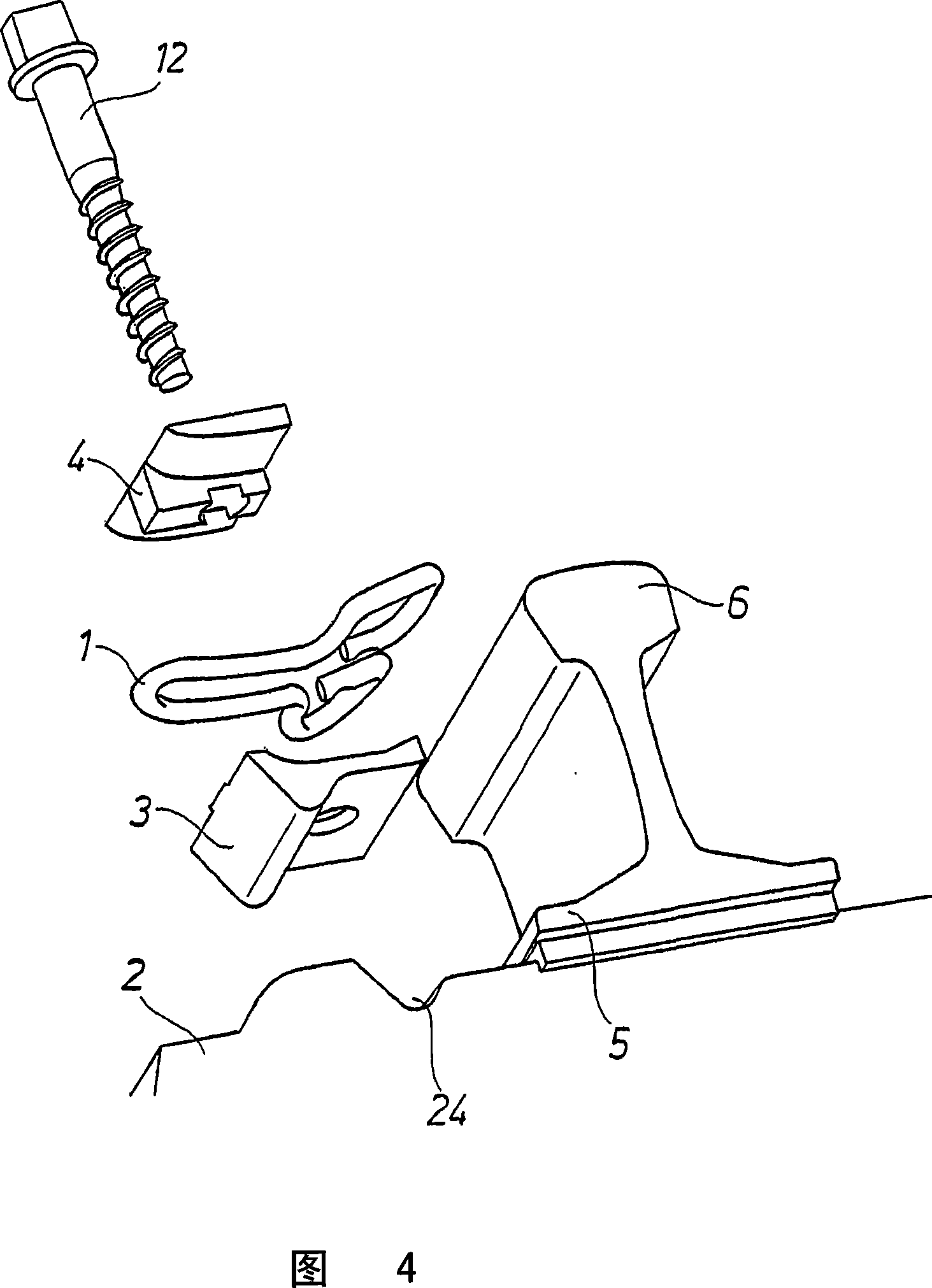
[0079] The basic structure of a non-positive connection elastic rail fastening for rail installations can be seen in FIGS. 1 to 4 . The track 6 must be fastened to the sleeper 2 or the track pad (see Figure 23). For this purpose, recesses 24 in the sleeper 2 are provided on the sleeper 2 , the shape of which corresponds to the protrusion of the support plate 3 resting on said sleeper 2 . The recesses 24 can be designed accordingly in the form of known angled guides or in other ways. The plate-shaped fastening anchor 4 is fastened to the support plate 3 or to the sleeper 2 by means of the sleeper bolt 12 . Arranged between the fastening anchor 4 and the support plate 3 is a clamping part 1 which, in its mounted state, exerts pressure on the rail foot 5 and thus fixes the rail 6 in the desired position.

[0080] As can be seen in FIG. 2 , the clamping part 1 is designed symmetrically, wherein the plane of symmetry 7 is arranged vertically and is perpendicular to the longitudin...


PUM


Abstract

A piezoelectric actuator having a frame portion includes a drive shaft for frictional engagement with an engageable barrel arm of a lens unit. First and second piezoelectric elements are supported on the frame portion, and provided with first and second ends of respectively the drive shaft. A drive pulse generator supplies the piezoelectric elements with a drive signal to expand or contract the piezoelectric elements, and moves the engageable barrel arm in an axial direction by an alternately repeating sequence of shifting the drive shaft at low and high speeds in the axial direction. In the shifting at the high speed, the piezoelectric elements shift the drive shaft in a backward direction quickly, to move the drive shaft in the backward direction relative to the engageable barrel arm being stationary with inertial force.

Description

technical field [0001] The invention relates to a non-positive connection-elastic rail fastening for rail installations, the rail fastening having a clamping part made of elastic material, in particular hardened spring steel, which is fixed in the installed state between a support plate arranged on the sleeper and the fixing anchor so that it exerts a supporting force on the rail foot of the rail for fixing the rail in place, wherein said clamping member is constructed symmetrically with respect to a vertically oriented plane of symmetry, This plane of symmetry is perpendicular to the longitudinal axis of the rail. Background technique [0002] A rail fastening of the type described is disclosed in DE 3400110C2. In this patent document a clamping part is used which is arranged between the support plate and the fastening anchor in the mounted state. The clamping part here has two arms which are designed as torsion elements. The torsion arm has two parallel side-by-side spr...

Claims


Application Information

Patent Timeline
Patent Type & Authority Patents(China)
IPC IPC(8): E01B9/30
CPCE01B9/303E01B9/30
Inventor K·-H·施韦德F·迈耶
Owner SCHWIHAG
Learn More